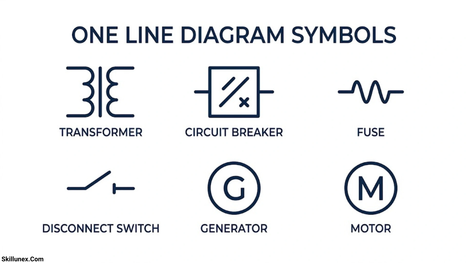
One line diagram symbols are essential for understanding electrical power systems and how different components work together. These symbols represent equipment such as transformers, circuit breakers, generators, switches, and other electrical devices in a simplified diagram. If you are an electrician, student, or engineer, learning these symbols can help you read and understand electrical systems more easily.
When you work with electrical drawings, you need to recognize the symbols used to represent different components and their connections. One line diagrams make complex electrical systems easier to understand by showing the main power distribution paths with simple lines and standard symbols. With the right knowledge, you can identify important components, follow electrical connections, and understand how power flows through a system.
In this guide, you will learn about common one line diagram symbols, their meanings, and their uses in electrical drawings. Whether you are a beginner or an experienced professional, this information can help you read diagrams more confidently and avoid common mistakes. By understanding these symbols, you can improve your electrical knowledge and work with power system diagrams more effectively.
What Is a One Line Diagram?
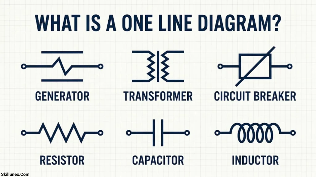
A one line diagram, also called a single-line diagram, is a simplified graphical representation of an electrical power distribution system. It shows the major electrical components and their interconnections without displaying every conductor, terminal, or internal connection.
A typical single-line diagram may include a utility power supply, transformer, main circuit breaker, busbar, outgoing feeders, protective relays, current transformers, and electrical loads.
For example, an industrial electrical system may receive medium-voltage power from a utility network. A transformer reduces the voltage to a suitable level, and a main circuit breaker distributes the power through a low-voltage busbar to motors, lighting circuits, and other equipment.
The single-line diagram illustrates these connections in a clear and organized format.
Why Is a Single Line Diagram Used?
A single-line diagram helps electrical professionals understand the overall structure of a power system without examining a large collection of detailed drawings.
Its main purposes include:
- Showing the flow of electrical power from the source to the loads.
- Identifying electrical equipment and its connections.
- Locating circuit breakers, disconnect switches, and protective devices.
- Displaying voltage levels, equipment ratings, and system configurations.
- Supporting fault analysis, short-circuit calculations, and protection coordination.
- Assisting with electrical installation, inspection, operation, and maintenance.
- Providing documentation for future modifications and system expansion.
Difference Between a Single-Line Diagram and a Wiring Diagram
A single-line diagram and a wiring diagram serve different purposes.
A single-line diagram shows the overall electrical system, including major equipment, feeders, busbars, and protection arrangements. A wiring diagram provides more detailed information about individual conductors, terminals, control connections, and component wiring.
For example, a single-line diagram may show a motor connected to a distribution bus through a circuit breaker and motor starter. The wiring diagram provides the detailed connections between the starter, contactor coil, overload relay, control switches, and motor terminals.
Both drawings are important, but they are used at different stages of electrical design, installation, and troubleshooting.
Common One Line Diagram Symbols and Their Meanings
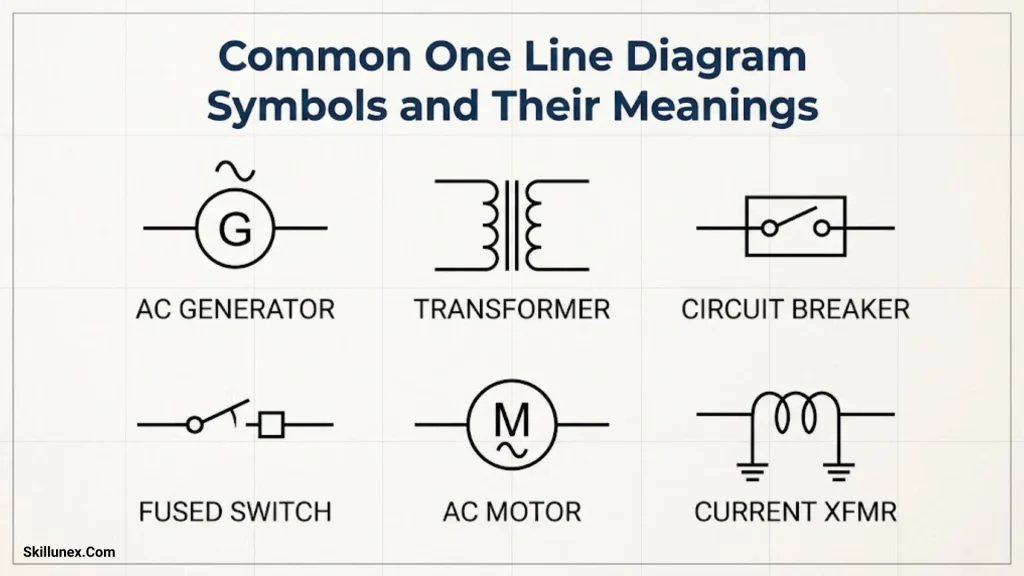
Electrical single-line diagrams use symbols to represent different types of equipment. The exact graphical appearance may vary according to the applicable standard, drafting convention, and project requirements.
The following sections explain common symbols and the functions of the equipment they represent.
Generator Symbol
A generator converts mechanical energy into electrical energy. In a single-line diagram, it is commonly represented by a circle containing the letter G or another generator identification mark.
Generators supply electrical power to utility networks, industrial facilities, hospitals, commercial buildings, and backup power systems.
Common applications include diesel generators, gas generators, hydroelectric generators, and other power-generation equipment.
Generator information shown on a diagram may include:
- Rated power in kW, kVA, or MVA.
- Rated voltage.
- Frequency.
- Power factor.
- Number of phases.
- Neutral grounding arrangement.
A generator symbol identifies the power source, while the associated labels provide the technical information required for system analysis and equipment selection.
Transformer Symbol
A transformer transfers electrical energy between circuits through electromagnetic induction. It is used to increase or decrease voltage levels in electrical power systems.
In conventional electrical drawings, a transformer may be represented by two coil symbols, sometimes separated by parallel lines indicating a magnetic core. Other standards and simplified drawings may use different graphical conventions.
Transformers are commonly classified as step-up transformers, step-down transformers, distribution transformers, and instrument transformers.
Important transformer information may include:
- Primary and secondary voltage ratings.
- Rated capacity in kVA or MVA.
- Winding connection, such as delta or star.
- Vector group.
- Percentage impedance.
- Neutral grounding arrangement.
For example, a transformer rated 11 kV/400 V reduces an 11 kV supply to a nominal 400 V three-phase distribution voltage. The actual operating voltage depends on the system and transformer arrangement.
Circuit Breaker Symbol
A circuit breaker is a switching and protective device designed to carry current under specified operating conditions and interrupt current when required.
Its symbol varies according to the drawing standard and breaker type. It is often represented by a standardized switching symbol and may be labeled CB, ACB, MCCB, or VCB.
Common circuit breaker types include:
- MCB: Miniature circuit breaker, commonly used in final distribution circuits.
- MCCB: Molded-case circuit breaker, used in distribution and industrial applications.
- ACB: Air circuit breaker, often used in low-voltage main distribution systems.
- VCB: Vacuum circuit breaker, commonly used in medium-voltage switchgear.
- SF6 circuit breaker: A breaker that uses sulfur hexafluoride gas in applicable high-voltage designs.
Circuit breakers help protect electrical installations against overcurrent and short-circuit conditions. Depending on their design and protection settings, they may also provide earth-fault protection.
Isolator or Disconnect Switch Symbol
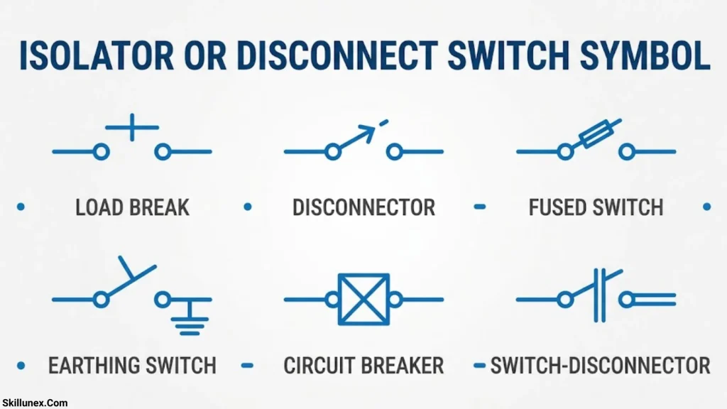
An isolator, also called a disconnect switch, is used to isolate electrical equipment from a power source so that maintenance or inspection can be performed safely.
It is commonly represented by a switch symbol with contacts that can be shown in an open or closed position.
Unlike a circuit breaker, a conventional isolator is generally not intended to interrupt load current or fault current unless specifically designed and rated for that duty.
Isolators are frequently installed in substations, transformer circuits, and medium- or high-voltage installations.
Before electrical equipment is serviced, the isolation procedure must follow the applicable safety requirements, including de-energization, lockout/tagout where required, and verification that the equipment is safe to work on.
Busbar Symbol
A busbar is a conductive component that provides a common connection point for incoming and outgoing electrical circuits.
In a single-line diagram, it is usually represented by a prominent horizontal or vertical line. Individual feeders connect to this line to receive or distribute electrical power.
Busbars are commonly found in distribution boards, switchgear, motor control centers, and electrical substations.
A single-line diagram may include several busbars to represent different voltage levels or separate sections of an electrical distribution system.
Busbar ratings can include continuous current capacity, short-time withstand current, peak withstand current, and rated voltage.
Fuse Symbol
A fuse protects an electrical circuit by melting its element when current exceeds the applicable operating limit for a sufficient period.
Fuse symbols vary between standards and drawing conventions. A fuse may be represented by a standardized rectangular or other prescribed graphical symbol.
Fuses are used in control circuits, distribution systems, transformer protection arrangements, and equipment circuits.
Unlike a resettable circuit breaker, a conventional fuse must be replaced after it operates. The correct fuse rating and breaking capacity are essential for effective protection.
Earth or Ground Symbol
An earth or ground symbol identifies a connection to an earthing system, protective grounding network, or designated reference point, depending on the symbol and drawing context.
A common protective earth symbol consists of a vertical line connected to horizontal lines of decreasing length. Other symbols are used for functional earth, chassis connections, or different grounding arrangements.
Earthing is important because it helps control dangerous touch voltages and provides an appropriate path for fault current in a properly designed protection system.
In electrical drawings, it is important to distinguish protective earthing from a neutral conductor. They serve different purposes and must be connected only as required by the applicable electrical system design and regulations.
Electric Motor Symbol
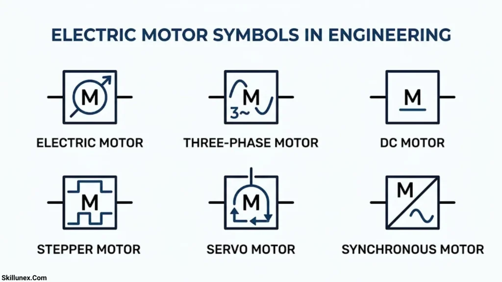
An electric motor converts electrical energy into mechanical energy. In a single-line diagram, it is commonly represented by a circle containing the letter M or another standardized motor symbol.
Motors are used in pumps, fans, compressors, conveyors, elevators, and industrial machinery.
A motor feeder may include a circuit breaker or fuse, contactor, overload relay, and motor starter. Larger motors may also use soft starters or variable-frequency drives.
Motor information on a diagram may include:
- Rated power in kW or horsepower.
- Rated voltage.
- Full-load current.
- Power factor.
- Efficiency.
- Starting method.
- Overload and short-circuit protection arrangements.
These details help engineers select appropriate cables, switching equipment, and protective devices.
Current Transformer (CT) Symbol
A current transformer measures current by producing a proportional secondary current suitable for metering or protective relays.
In a single-line diagram, a CT may be shown around or adjacent to a conductor, or as a transformer-like instrument symbol, depending on the drawing convention.
Current transformers are widely used for ammeters, energy meters, overcurrent relays, differential protection, and earth-fault protection.
Important CT information includes its ratio, accuracy class, rated burden, and protection or metering application.
For example, a CT with a ratio of 200/5 A is designed to provide a nominal secondary current of 5 A when the primary current is 200 A under its specified operating conditions.
Safety note: A conventional CT secondary must not be left open-circuited while primary current is flowing, because a dangerously high secondary voltage may develop. CT work must be performed by qualified personnel using approved procedures.
Potential Transformer or Voltage Transformer Symbol
A potential transformer (PT), also called a voltage transformer (VT), reduces a high voltage to a suitable value for measurement, monitoring, and protection.
Its symbol may resemble a transformer symbol and may include labels such as PT or VT.
Voltage transformers are used with voltmeters, energy meters, synchronizing equipment, and protective relays.
A voltage transformer can provide a scaled-down voltage signal to equipment that cannot be connected directly to the primary high-voltage circuit.
Its ratio, accuracy class, rated burden, insulation level, and connection arrangement are important when designing a metering or protection system.
Protective Relay Symbol
A protective relay detects abnormal electrical conditions and initiates an appropriate response, such as commanding a circuit breaker to trip.
In a single-line diagram, a relay may appear as a labeled rectangle, a device identifier, or a standardized function symbol.
Common protection functions include:
- Overcurrent protection.
- Earth-fault protection.
- Differential protection.
- Under-voltage protection.
- Over-voltage protection.
- Under-frequency and over-frequency protection.
- Thermal overload protection.
- Reverse-power protection.
Protective relays are selected according to the equipment being protected and the system’s fault characteristics.
In many installations, CTs and VTs provide measurement signals to the relay, which then operates the associated circuit breaker when the configured protection criteria are met.
Electrical Load Symbol
An electrical load represents equipment or a circuit that consumes electrical power.
Loads may be shown using a motor symbol, lighting symbol, resistor symbol, distribution-board designation, or a general load symbol, depending on the type of equipment and the drawing standard.
Common electrical loads include lighting, heating equipment, motors, office equipment, industrial machinery, and power distribution panels.
Load labels may show connected power, demand power, current, voltage, power factor, and feeder identification.
Accurate load information is important for cable sizing, transformer selection, voltage-drop calculations, and circuit protection design.
Additional One Line Diagram Symbols Used in Electrical Systems
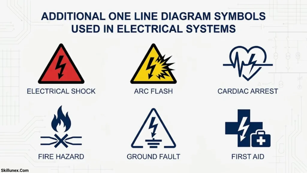
Beyond the basic symbols, many electrical power systems use additional devices to represent switching, metering, power conversion, and protection functions.
Contactor Symbol
A contactor is an electrically controlled switching device used to operate motors, heaters, lighting circuits, and other electrical loads.
It is often identified by the label KM or another project-specific designation. Its main contacts and control coil may be shown separately in detailed control diagrams.
Contactors are commonly used in direct-on-line motor starters, star-delta starters, and automatic control systems.
A contactor is not normally a substitute for a circuit breaker because its ability to interrupt short-circuit current and provide protective functions is different.
Overload Relay Symbol
An overload relay protects motors against sustained overcurrent conditions that may cause overheating.
It is commonly installed as part of a motor starter and is represented by an appropriate protection-device symbol or labeled component.
An overload relay typically works with a contactor to disconnect the motor when an overload condition is detected.
Motor overload protection and short-circuit protection are separate functions, although coordinated devices may provide both within a complete motor protection arrangement.
Lightning Arrester or Surge Arrester Symbol
A surge arrester protects electrical equipment by limiting transient overvoltages caused by lightning or switching events.
It is commonly installed in substations, transformer installations, overhead-line connections, and other exposed electrical systems.
In a single-line diagram, it may be identified by an arrester symbol or the abbreviation LA or SA.
Surge arresters help reduce the risk of insulation damage but do not eliminate every possible overvoltage hazard.
Capacitor Bank Symbol
A capacitor bank is used to provide reactive power compensation and improve power factor in appropriate electrical installations.
It is commonly represented by capacitor symbols or a labeled capacitor-bank block.
Capacitor banks can reduce reactive power drawn from the supply and help improve voltage conditions when correctly designed.
Their switching arrangements must account for inrush current, harmonic conditions, discharge requirements, and the possibility of resonance.
Variable Frequency Drive (VFD) Symbol
A variable-frequency drive controls the speed of an AC motor by adjusting the frequency and voltage supplied to it.
In a single-line diagram, a VFD may be represented by a labeled rectangular block or a power conversion symbol.
VFDs are used in pumps, fans, compressors, conveyors, and process-control applications.
They can improve process control and reduce energy consumption in suitable variable-torque applications. Their use also requires consideration of harmonics, motor insulation, electromagnetic compatibility, and protection requirements.
Rectifier and Inverter Symbols
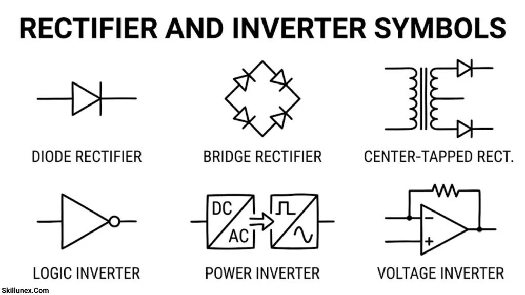
A rectifier converts alternating current (AC) into direct current (DC), while an inverter converts DC into AC.
These devices are used in battery systems, solar photovoltaic installations, uninterruptible power supplies, motor drives, and other power-electronic applications.
Single-line diagrams often show rectifiers and inverters as labeled blocks with AC and DC connections.
Their ratings and connection details are important when evaluating power quality, conversion efficiency, and system compatibility.
Battery Symbol
A battery supplies or stores direct-current electrical energy. Its symbol may use alternating long and short parallel lines or a labeled battery-system block, depending on the diagram type.
Batteries are used in emergency lighting, substations, telecommunications, control systems, solar installations, and uninterruptible power supplies.
Battery-system information may include DC voltage, capacity in ampere-hours, battery chemistry, and the associated charger or inverter.
Photovoltaic Solar Panel Symbol
A photovoltaic (PV) panel converts sunlight into electrical energy and is usually represented by a solar-panel symbol or a labeled PV block.
A solar single-line diagram may include PV modules, string connections, combiner boxes, DC isolators, surge protection, inverters, AC isolators, and the point of connection to the electrical distribution system.
Grid-connected solar systems must also incorporate the protection, isolation, and anti-islanding arrangements required by the applicable regulations and equipment specifications.
Energy Meter Symbol
An energy meter measures electrical energy consumption or production, usually in kilowatt-hours (kWh).
It may be represented by a meter symbol or a labeled block such as EM, kWh meter, or another project-specific identifier.
Meters are installed in residential distribution boards, commercial buildings, industrial facilities, and utility connections.
Depending on the installation, a meter may be connected directly to the circuit or through instrument transformers.
Neutral Connection Symbol
The neutral conductor provides a current-carrying return path in applicable AC systems and is associated with the system’s electrical reference point.
A single-line diagram may show the neutral using a labeled conductor, a connection point, or a specific neutral designation.
Neutral and protective earth conductors must not be treated as interchangeable. Their connection arrangements depend on the system earthing method and applicable electrical requirements.
How to Read a One Line Diagram Step by Step
Understanding individual symbols is only the first step. To interpret a complete single-line diagram, it is necessary to follow the connections between components and identify the system’s operating arrangement.
Identify the Power Source
Start by locating the utility incomer, generator, solar inverter, or another power source.
Check the source voltage, frequency, rated capacity, and any available short-circuit information. These details establish the starting point for understanding the electrical system.
Follow the Main Electrical Path
Trace the connection from the source to the main switching equipment, transformer, and busbar.
Identify how power enters the installation and which devices can disconnect or isolate each section.
A typical distribution path may be:
Utility supply → Incoming circuit breaker → Transformer → Main low-voltage switchboard → Outgoing feeders → Electrical loads.
The actual order depends on the installation. For example, a transformer may be located upstream of the incoming low-voltage circuit breaker.
Identify Voltage Levels
Check the voltage labels associated with transformers, switchgear, busbars, and feeders.
For example, an industrial installation may use an 11 kV incoming supply and a transformer rated 11 kV/400 V to supply low-voltage equipment.
Voltage levels help determine the appropriate insulation, switching equipment, cable ratings, and protection arrangements.
Locate Protection and Switching Devices
Identify circuit breakers, fuses, isolators, CTs, VTs, and protective relays.
Check which equipment each device protects and whether its operation is controlled manually, automatically, or through a protection system.
Do not assume that every switch symbol represents a circuit breaker or that every protection device provides the same functions.
Identify Outgoing Feeders and Loads
Follow each outgoing feeder from the busbar to its destination.
A feeder may supply a motor control center, distribution board, transformer, capacitor bank, or individual machine.
Review the equipment labels, rated currents, connected loads, and any cable or feeder identification provided.
Check the Drawing Legend and Notes
Always examine the drawing legend, abbreviations, general notes, and equipment schedule.
A legend explains the specific graphical conventions used in the project. It is especially important when the drawing combines IEC, IEEE, ANSI, or company-specific conventions.
Review the Equipment Ratings
Check the voltage, current, power, breaking capacity, transformer impedance, and protective-device settings where they are provided.
These details are necessary for technical analysis and cannot be determined reliably from the symbols alone.
Example of a Simple Electrical Single-Line Diagram
Consider a small industrial facility supplied by an 11 kV utility network. The utility supply feeds an 11 kV switchgear assembly, which connects to an 11 kV/400 V distribution transformer. The transformer supplies a 400 V main switchboard, which distributes power to motor feeders, lighting distribution boards, and general electrical loads.
The arrangement can be described as follows:
Utility supply → Medium-voltage circuit breaker → Transformer → Main low-voltage circuit breaker → Busbar → Outgoing feeders → Loads
This sequence is a simplified example, not a universal arrangement. Actual installations may include CTs, VTs, surge arresters, earthing switches, multiple bus sections, standby generators, automatic transfer switches, and other equipment.
When reviewing the drawing, verify the equipment ratings, connection points, switching positions, and protective functions rather than relying solely on the order of the labels.
Standards for One Line Diagram Symbols
Standardization helps engineers and technicians interpret electrical drawings consistently. However, the exact symbol used for a component may differ depending on the standard, application, and project drafting rules.
IEC 60617
IEC 60617 provides graphical symbols for use in electrotechnical diagrams. It is an important reference for electrical design documentation in many countries and industries.
Engineers should consult the relevant symbol entries and applicable project requirements when preparing or interpreting drawings.
IEEE 315
IEEE 315 is a historical reference for graphical symbols used in electrical and electronics diagrams. Before specifying it for a project, verify the applicable edition, current status, and whether a newer or more suitable standard is required.
ANSI and NFPA Conventions
North American electrical drawings may use ANSI-related symbol conventions and applicable NFPA standards, depending on the drawing type and industry.
The precise requirements should be confirmed against the current standards adopted for the project.
Why the Drawing Legend Matters
Even when a project follows an established standard, its legend may define abbreviations, equipment tags, line types, and project-specific conventions.
Always prioritize the approved project documentation and applicable requirements over assumptions based on a symbol’s appearance.
Common Mistakes When Reading One Line Diagram Symbols
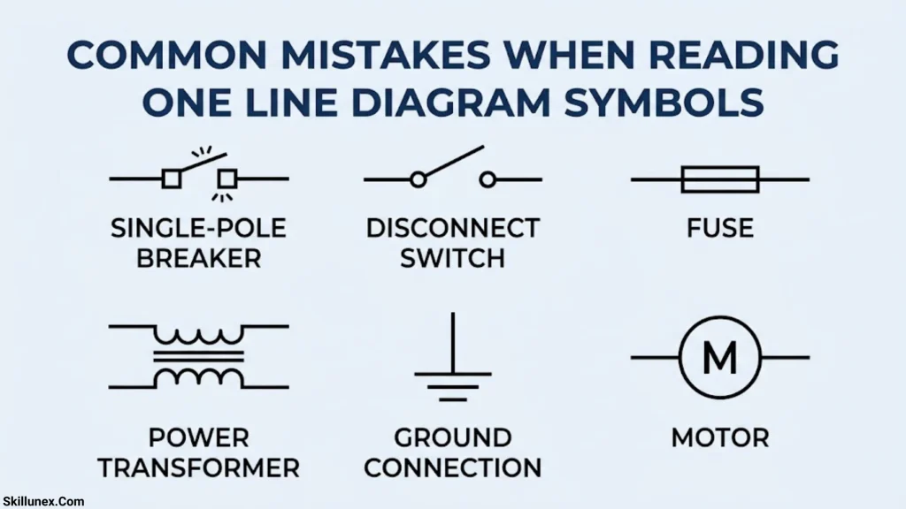
Misinterpreting electrical symbols can lead to incorrect assumptions about equipment functions, protection arrangements, and safe operating procedures.
Confusing an Isolator With a Circuit Breaker
An isolator is generally intended to provide isolation, while a circuit breaker is designed to make or interrupt current within its rated operating capabilities.
The two devices should not be assumed to perform the same function.
Treating Neutral and Earth as the Same Conductor
Neutral and protective earth serve different purposes. Their connections must follow the system design and applicable electrical regulations.
Incorrectly connecting them can create dangerous touch voltages and interfere with protective-device operation.
Ignoring Equipment Ratings
A symbol identifies a component but does not establish its voltage rating, current capacity, breaking capacity, or protection settings.
Always read the associated labels, schedules, and technical documentation.
Assuming Every Diagram Uses Identical Symbols
Symbol conventions can vary between standards, software packages, manufacturers, and organizations.
The project legend should be checked before drawing conclusions about an unfamiliar symbol.
Overlooking Normally Open and Normally Closed Positions
Switches and circuit breakers may be shown in a particular operating position. That position does not necessarily mean the equipment will remain in that state during every operating condition.
Check the drawing notes, switching philosophy, and control documentation when operating states are important.
Relying on a Single Line Diagram for Detailed Wiring
A single-line diagram does not usually show every conductor, terminal, interlock, or control connection.
Use wiring diagrams, schematic diagrams, cable schedules, and equipment manuals when detailed connections are required.
Applications of One Line Diagrams in Electrical Engineering
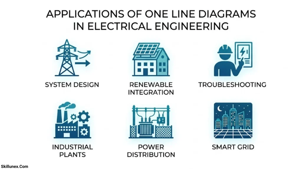
Single-line diagrams are used across the electrical power industry because they communicate the structure of a system efficiently.
Power Generation Plants
Power plants use single-line diagrams to represent generators, generator breakers, step-up transformers, auxiliary supplies, and connections to the transmission network.
Electrical Substations
Substation diagrams show incoming and outgoing feeders, busbars, circuit breakers, disconnect switches, transformers, instrument transformers, and protection arrangements.
Industrial Facilities
Factories use single-line diagrams to document transformers, main switchboards, motor control centers, production equipment, standby generators, and other distribution equipment.
Commercial and Residential Buildings
Building electrical diagrams show utility incomers, distribution boards, transformers where applicable, standby supplies, and major electrical loads.
Solar Power Systems
Solar single-line diagrams represent PV arrays, inverters, protection devices, isolators, meters, and connections to the building distribution system or utility network.
Emergency Power and UPS Systems
Hospitals, data centers, commercial buildings, and industrial facilities use these diagrams to document standby generators, battery systems, uninterruptible power supplies, automatic transfer switches, and essential-load distribution.
Frequently Asked Questions
What are one line diagram symbols?
One line diagram symbols are standardized graphical representations of electrical equipment used in single-line diagrams. They identify components such as generators, transformers, circuit breakers, busbars, isolators, protective relays, and loads.
What is the difference between a one line diagram and a single-line diagram?
There is generally no difference. Both terms refer to a simplified electrical diagram that represents the main components and connections of a power system, often using one line for a three-phase circuit.
Why is a single line used to represent a three-phase system?
A single line simplifies the drawing by representing the overall three-phase circuit without showing all three phase conductors separately. Additional labels and notes provide the information needed to understand the system.
Which standard is used for electrical one line diagram symbols?
IEC 60617 is an important international reference for electrotechnical graphical symbols. Other standards and conventions may be used depending on the country, industry, and project requirements. The drawing legend should always be checked.
What are the most important symbols to learn first?
Start with the symbols for generators, transformers, busbars, circuit breakers, disconnect switches, fuses, earth connections, current transformers, voltage transformers, protective relays, motors, and electrical loads.
These components appear frequently in distribution systems and provide a foundation for understanding more complex diagrams.
Can a single line diagram show cable sizes and equipment ratings?
Yes. A detailed single-line diagram may include cable sizes, conductor types, equipment ratings, voltage levels, transformer capacities, breaker ratings, and protective-device information. However, the amount of detail varies by project.
What is the difference between a CT and a VT?
A current transformer provides a scaled current signal for metering and protection, while a voltage transformer provides a scaled voltage signal. Both allow measuring and protection equipment to monitor electrical systems within their specified operating limits.
Is a single line diagram sufficient for electrical installation?
Not always. It provides an overview of the power system, but installation may also require wiring diagrams, schematic drawings, cable schedules, equipment layouts, termination details, and other approved documentation.
Which software is used to create single-line diagrams?
Electrical professionals may use AutoCAD, AutoCAD Electrical, EPLAN, ETAP, EasyPower, and other electrical design or power-system analysis tools. The appropriate software depends on whether the task involves drafting, protection studies, short-circuit analysis, or broader electrical system design.
Conclusion
One line diagram symbols are fundamental to understanding electrical power distribution systems. They provide a simplified and consistent way to represent generators, transformers, circuit breakers, busbars, isolators, protective relays, instrument transformers, motors, and other electrical equipment.
Learning these symbols makes it easier to follow power flow, identify protection devices, understand equipment connections, and interpret electrical engineering drawings. A thorough understanding also requires knowledge of equipment ratings, system voltage levels, protection arrangements, and the applicable drawing standards.
For accurate interpretation, always check the project legend, equipment labels, approved drawings, and relevant electrical standards. Detailed wiring diagrams and equipment documentation should also be consulted whenever the task requires information beyond the overall power system arrangement.
If you are an electrical engineering student, electrician, design engineer, or maintenance professional, mastering one line diagram symbols is an important step toward working confidently with electrical installations.

I’m Adrian Holloway, a writer and researcher who enjoys exploring the stories, meanings, and interesting facts behind the subjects people search for every day. I’m especially interested in symbols, nature, lakes, places, and cultural topics that help readers understand the world from a different perspective.
I believe useful content should be simple, accurate, and enjoyable to read. When I research a topic, I focus on finding meaningful details and presenting them in a way that makes information easy to understand.
My goal is to create helpful articles that answer real questions while encouraging readers to discover something new with every visit.
Books by Adrian Holloway
The Language of Symbols: Meanings, Stories & Traditions
Hidden Wonders of Nature: Lakes, Landscapes & Discovery