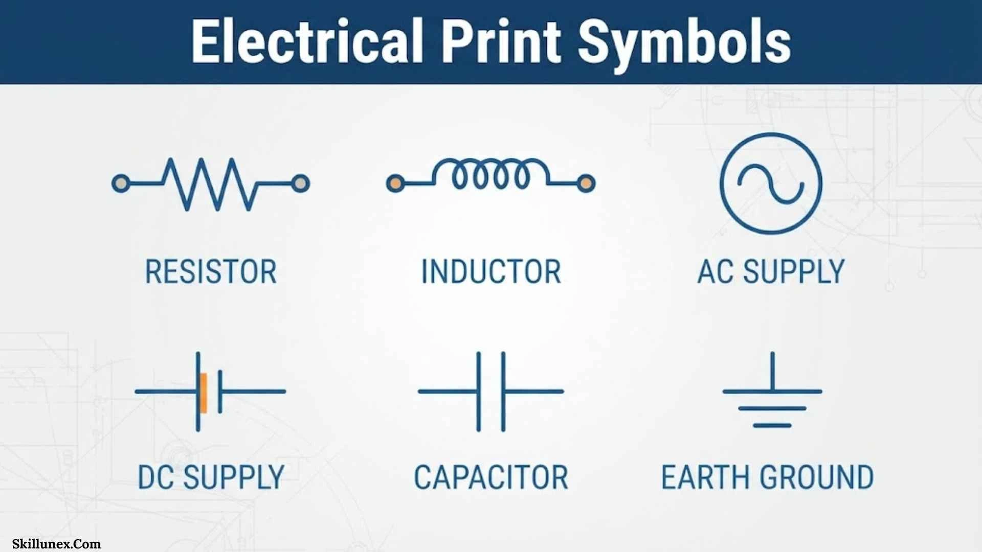
Electrical print symbols are the visual language used to represent electrical components, connections, controls, and equipment on technical drawings. If you can recognize these symbols, you can understand an electrical plan without reading every component name.
When you first look at an electrical print, the combination of lines, circles, letters, numbers, and unfamiliar shapes can seem confusing. However, once you understand the most common electrical print symbols, you can start tracing circuits, identifying components, and understanding how an electrical system is intended to work.
I’ll walk you through the major electrical symbols, their meanings, common applications, drawing conventions, standards, and practical ways you can read an electrical print. You’ll also find tables and examples that make the information easier to use as a reference.
What Are Electrical Print Symbols?
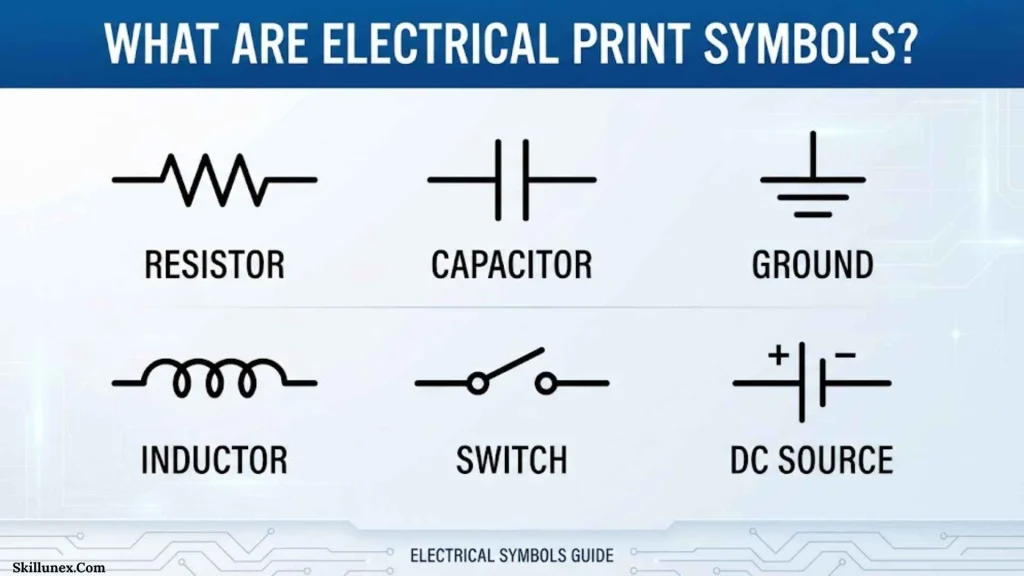
Electrical print symbols are standardized or project-specific graphical representations of electrical devices and functions used on electrical drawings.
Instead of writing the complete name of every component, an engineer or designer uses a symbol. This keeps a drawing organized and allows you to understand a large amount of technical information in a relatively small space.
For example, a drawing might use a symbol to represent a:
- Switch
- Light fixture
- Receptacle
- Circuit breaker
- Fuse
- Transformer
- Motor
- Relay
- Resistor
- Capacitor
- Diode
- Ground connection
- Battery
- Electrical panel
- Measuring instrument
The symbol normally works together with labels, circuit numbers, conductor lines, notes, schedules, and a drawing legend.
Why Electrical Symbols Are Used
Electrical systems can contain hundreds or thousands of components. If every device were written out in full, the drawing would quickly become difficult to read.
Symbols provide a compact way to communicate information.
They help you:
- Identify electrical components quickly.
- Understand circuit relationships.
- Trace electrical connections.
- Read wiring diagrams.
- Interpret electrical blueprints.
- Plan installations.
- Troubleshooting equipment.
- Communicate designs between professionals.
- Document existing electrical systems.
- Understand control and power circuits.
A good electrical drawing doesn’t just tell you what a component is. It can also show you where the component belongs, what it connects to, and how it interacts with other components.
How Electrical Print Symbols Work
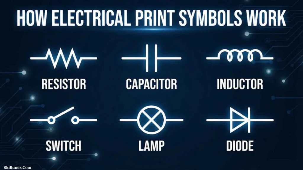
An electrical symbol rarely works by itself. You normally need to interpret several pieces of information together.
For example, if you see a switch symbol near a lighting fixture, the connecting line can help you determine which light the switch controls.
Similarly, if you see a circuit breaker followed by a motor symbol, you can identify a basic relationship between circuit protection and the motor load.
Symbols, Lines, and Labels
Three things are especially important when reading an electrical print:
| Drawing Element | What It Tells You |
| Symbol | Identifies a component or function |
| Line | Shows an electrical or functional connection |
| Label | Provides additional identification or technical information |
A symbol might tell you that a device is a motor, while a label may tell you the motor number, voltage, phase, or circuit reference.
The Drawing Legend
Always check the electrical drawing legend before assuming what a symbol means.
Different industries, companies, software packages, and drawing standards can use different graphical conventions. A symbol that looks familiar may have a different meaning in a particular project.
If you’re working from a professional electrical print, the project legend should take priority over a generic symbol chart.
Common Electrical Print Symbols
The following electrical print symbols appear frequently in residential, commercial, industrial, and electronic drawings.
| Electrical Component | Common Function |
| Switch | Opens or closes a circuit |
| Lamp | Represents a light source |
| Receptacle | Provides an electrical connection for equipment |
| Ground | Indicates grounding or earth connection |
| Fuse | Provides overcurrent protection |
| Circuit breaker | Opens a circuit under specified fault or overcurrent conditions |
| Transformer | Transfers energy between circuits and changes voltage |
| Motor | Converts electrical energy into mechanical energy |
| Resistor | Opposes or limits current |
| Capacitor | Stores electrical energy |
| Inductor | Stores energy in a magnetic field |
| Diode | Primarily permits current in one direction |
| Relay | Uses one circuit to control another |
| Battery | Provides electrical DC energy |
| Ammeter | Measures current |
| Voltmeter | Measures voltage |
| Contactor | Switches power circuits, often for motors and other loads |
| Terminal block | Provides organized connection points |
| Antenna | Represents an antenna or radiating element |
| Generator | Produces electrical energy |
Electrical Switch Symbols
Switches control whether current can flow through a circuit or whether a particular electrical function is activated.
You’ll find switch symbols in lighting plans, control circuits, industrial schematics, and equipment diagrams.
Single Pole Switch
A single-pole switch is commonly used to control a light or another load from one location.
In a residential plan, you might find the switch near a door with a line or circuit reference connecting it to the controlled lighting.
The exact graphical symbol depends on the drawing convention being used.
Double Pole Switch
A double-pole switch operates two conductors or circuit poles simultaneously.
You may encounter this type of switch where a circuit requires simultaneous switching of multiple conductors.
Three Way Switch
A three-way switching arrangement allows you to control a light or load from two locations.
This arrangement is common in:
- Stairways
- Hallways
- Rooms with two entrances
- Large living areas
When you read a drawing containing multiple switches, don’t look only at the symbol. Follow the wiring connections to understand how the switches work together.
Four Way Switch
A four-way switching arrangement can be used when a load needs to be controlled from three or more locations.
The complete circuit normally combines four-way and three-way switching devices.
Electrical Outlet and Receptacle Symbols
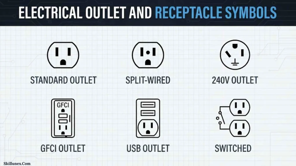
Receptacle symbols identify locations where electrical equipment can be connected to a power supply.
In residential and commercial electrical plans, you may see receptacles represented using specific symbols or abbreviations.
Common types include:
- Standard receptacles
- Duplex receptacles
- GFCI receptacles
- Weather-resistant receptacles
- Floor receptacles
- Outdoor receptacles
- Dedicated equipment receptacles
- Appliance outlets
If you’re reading a floor plan, the location of each receptacle can be just as important as the electrical circuit connected to it.
GFCI Receptacle Symbols
A ground-fault circuit-interrupter receptacle provides protection against certain ground-fault conditions.
You may find these receptacles in areas where electrical safety requirements are more stringent, such as locations near water.
The exact symbol and notation should always be confirmed using the project legend and applicable electrical code requirements.
Electrical Lighting Symbols
Lighting symbols identify fixtures and lighting equipment on electrical plans.
You may encounter symbols representing:
- Ceiling-mounted lights
- Recessed lights
- Pendant lights
- Wall-mounted fixtures
- Emergency lighting
- Exit lighting
- Exterior lighting
- Floodlights
- Spotlights
- Fluorescent or linear fixtures
A lighting symbol tells you that a fixture exists at a particular location, but additional information may be needed to understand its exact type, rating, mounting arrangement, or control method.
Lighting Control Symbols
Lighting plans often show switches separately from fixtures.
When you’re reading the drawing, look for the relationship between:
Power source → switch → lighting fixture
This basic sequence can help you understand how a lighting circuit operates.
Ground Electrical Print Symbols
Ground symbols are among the most important electrical symbols because grounding plays a major role in electrical safety and system operation.
However, not every ground-related symbol means exactly the same thing.
Depending on the drawing, you may encounter symbols or designations for:
- Protective earth
- Chassis ground
- Signal ground
- Functional ground
- Earth connection
Always check the project documentation because grounding conventions can vary between electrical, electronic, industrial, and control drawings.
Why Ground Symbols Matter
Grounding can provide a reference point for electrical systems and can provide a path associated with fault protection.
When you see a ground symbol, don’t simply assume that every ground connection is physically identical. You should consider the drawing’s grounding scheme and documentation.
Circuit Breaker Symbols
Circuit breakers are protective devices designed to interrupt electrical current under specified abnormal conditions.
On electrical prints, breaker symbols can appear in:
- Distribution panels
- Switchboards
- Control panels
- Motor circuits
- Industrial power systems
- Building electrical plans
A breaker may also have a circuit number, rating, pole information, or other designation beside it.
Circuit Breaker Information
A drawing may provide information such as:
- Breaker identification
- Number of poles
- Current rating
- Voltage
- Circuit number
- Panel designation
- Connected load
The graphical symbol alone usually doesn’t provide all of this information, so you should read the accompanying notes and schedules.
Fuse Symbols
A fuse is an overcurrent protection device designed to interrupt a circuit when current exceeds its specified characteristics.
Fuse symbols are common in:
- Control circuits
- Power supplies
- Industrial equipment
- Automotive electrical systems
- Electronic circuits
- Distribution equipment
The drawing may identify the fuse using a reference designation and rating.
For example, the drawing could identify a fuse as F1, while the associated schedule or specification provides the fuse rating and type.
Transformer Symbols
A transformer transfers electrical energy between circuits through electromagnetic induction and can be used to change AC voltage levels or provide electrical isolation.
Transformer symbols commonly show winding relationships.
You may encounter:
- Step-up transformers
- Step-down transformers
- Isolation transformers
- Control transformers
- Current transformers
- Voltage or potential transformers
How to Read a Transformer Symbol
When you see a transformer on a schematic, look at both sides of the symbol.
One side represents one winding or circuit, while the other side represents another winding or circuit. Additional markings may identify voltage, phase, turns ratio, or other technical characteristics.
Motor Electrical Print Symbols
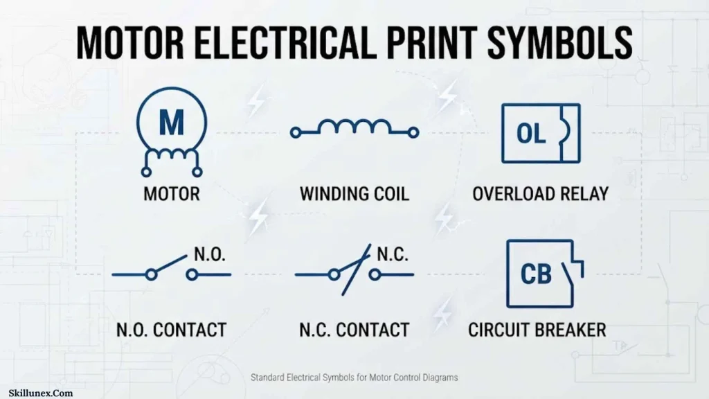
Motor symbols represent electrical machines that convert electrical energy into mechanical energy.
Motors are especially common in industrial electrical prints.
You may find motors connected to:
- Motor starters
- Contactors
- Overload protection
- Disconnect switches
- Variable frequency drives
- Control relays
- Push buttons
- Sensors
Motor Circuit Example
A simplified motor circuit can be understood as:
Power source → protection → switching/control → motor
When you follow the drawing in this order, you can often understand the basic function of the system more easily.
Industrial drawings may provide additional information about motor voltage, phase, horsepower, starter type, overload settings, and control method.
Resistor Symbols
A resistor limits or controls electrical current and can also be used to create voltage relationships in a circuit.
Depending on the drawing standard, you may see a resistor represented by a zigzag line or a rectangular box.
Resistors are commonly used in:
- Control circuits
- Electronic circuits
- Voltage dividers
- Signal conditioning
- Current limiting
- Measurement circuits
The resistance value is normally provided using a number and unit, such as ohms.
Capacitor Symbols
A capacitor stores electrical energy in an electric field.
The basic capacitor symbol is generally represented by two conductive plates, although the exact appearance can change for specialized capacitor types.
Capacitors can be used for:
- Filtering
- Energy storage
- Motor applications
- Power-factor correction
- Signal coupling
- Timing circuits
- Noise suppression
Polarized Capacitor Symbols
Some capacitors are polarized, meaning they have designated positive and negative terminals.
If you see a polarity marking on a capacitor symbol, you should pay close attention to it because correct polarity can be essential to proper circuit operation and component safety.
Inductor Symbols
An inductor stores energy in a magnetic field when current flows through it.
The standard representation commonly resembles a coil.
Inductors are used in:
- Filters
- Power supplies
- Transformers
- Motor circuits
- Signal-processing circuits
- Electromagnetic applications
When you see an inductor symbol, look at its connections and surrounding components to understand its role in the circuit.
Diode Symbols
A diode is a semiconductor device that primarily allows current to flow in one direction.
Diode symbols are common in electronic and electrical schematics.
You may encounter symbols for:
- Standard diodes
- LEDs
- Zener diodes
- Photodiodes
- Schottky diodes
- Varactor diodes
LED Symbol
An LED, or light-emitting diode, is typically represented by a diode symbol with additional arrows indicating emitted light.
If you’re reading an electronic schematic, recognizing the difference between a standard diode and an LED can help you understand both the electrical and functional purpose of the component.
Relay Symbols
A relay allows an electrical circuit to control another circuit.
A relay symbol commonly represents a coil and one or more associated contacts.
Common contact arrangements include:
- Normally open
- Normally closed
- Changeover
Relays are widely used in:
- Industrial automation
- Control panels
- Automotive systems
- HVAC controls
- Safety systems
- Machine controls
When reading a relay diagram, look for the relay’s reference designation and then find all contacts carrying the same designation. This lets you understand where the relay influences the circuit.
Contactor Symbols
A contactor is an electrically controlled switching device commonly used for power circuits.
Contactors are frequently used to control:
- Motors
- Heating equipment
- Lighting loads
- Industrial machinery
On a control schematic, you may see a contactor coil in the control circuit and associated power contacts in the load circuit.
This separation is important because the control circuit can command the contactor while the power contacts handle the larger load circuit.
Battery Symbols
Battery symbols identify DC electrical power sources.
A traditional battery symbol uses alternating long and short lines to represent cells or terminals.
Battery symbols may appear in:
- Control systems
- Electronic devices
- Automotive circuits
- Backup systems
- Emergency equipment
- Portable equipment
Pay attention to polarity markings because positive and negative connections can be important in DC circuits.
Generator Symbols
A generator converts mechanical energy into electrical energy.
Generator symbols are commonly used in power-generation and distribution drawings.
You may find generators associated with:
- Transfer switches
- Emergency power systems
- Distribution panels
- Protection equipment
- Synchronizing equipment
- Loads
A generator drawing can be much more complex than its basic symbol because additional equipment is required to control, protect, and distribute the generated electrical power.
Measurement Device Symbols
Electrical prints can include instruments used to measure electrical quantities.
| Device | Measures |
| Ammeter | Electrical current |
| Voltmeter | Voltage |
| Wattmeter | Electrical power |
| Ohmmeter | Resistance |
| Frequency meter | Frequency |
| Power-factor meter | Power factor |
You might see these instruments in laboratory circuits, industrial control panels, switchgear, and power-distribution systems.
Electrical Print Symbols for Wiring
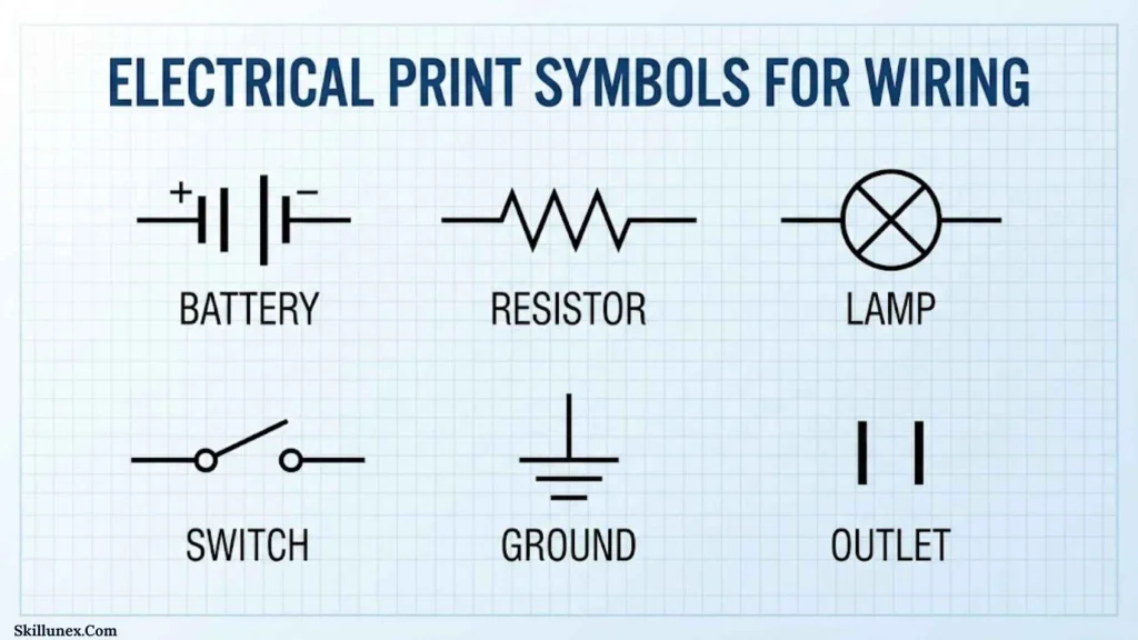
Electrical symbols identify components, but the lines between those symbols are equally important.
A line generally represents a conductor, connection, or other relationship depending on the drawing type.
Connected Wires
When conductors are connected, the drawing convention should make that relationship clear.
A connection may be shown using a junction or connection dot, depending on the drafting convention.
Crossing Wires
Two lines crossing each other don’t automatically mean that they are electrically connected.
This is one of the mistakes beginners commonly make.
You should check whether the drawing uses a junction dot or another convention to indicate an actual connection.
Wire Numbers
Large electrical prints may assign numbers to wires.
Wire numbers allow you to identify the same conductor or circuit relationship across different parts of a drawing.
This becomes especially useful in industrial control panels where a single circuit can span several pages.
Electrical Panel Symbols
Electrical panels contain multiple components, so panel drawings often combine many symbols and labels.
A panel drawing may include:
- Main circuit breaker
- Branch circuit breakers
- Disconnects
- Fuses
- Contactors
- Relays
- Terminal blocks
- Grounding connections
- Neutral connections
- Busbars
- Control devices
- Metering equipment
Panel Schedules
A panel schedule can provide information about circuits connected to a panel.
You might find:
- Circuit number
- Breaker rating
- Description
- Load information
- Phase information
- Panel identification
When you’re reviewing a building electrical plan, don’t rely only on the floor plan. The panel schedule can provide important additional information.
Electrical Print Symbols for Residential Wiring
Residential electrical plans usually show the location and type of electrical devices throughout a building.
You may find symbols for:
- Light fixtures
- Wall switches
- Ceiling fans
- Receptacles
- GFCI receptacles
- Smoke alarms
- Doorbells
- Exterior lights
- Electrical panels
- Dedicated appliance outlets
For example, if you’re reviewing a house plan, you can use the symbols to identify where lighting fixtures and receptacles are intended to be installed.
Residential Electrical Plans
A residential electrical drawing may combine architectural information with electrical symbols.
This means you should pay attention to:
- Room names
- Door locations
- Walls
- Fixture locations
- Switch locations
- Receptacle locations
- Circuit references
- Panel references
The physical location of a symbol is often just as important as the symbol itself.
Electrical Print Symbols for Commercial Buildings
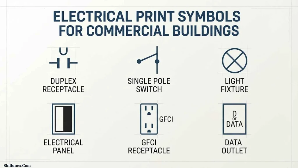
Commercial electrical drawings can be significantly more detailed than residential plans.
A commercial project may use separate drawings for:
- Lighting
- Power distribution
- Emergency power
- Fire alarm
- Communications
- Data systems
- Security
- HVAC controls
- Equipment connections
If you’re reading a commercial project, you may need to cross-reference several drawing sheets to understand a complete system.
Electrical Print Symbols for Industrial Systems
Industrial electrical drawings often contain more complex control and power symbols.
You may encounter:
- Motors
- Contactors
- Relays
- Push buttons
- Selector switches
- Limit switches
- Proximity sensors
- Solenoid valves
- PLC inputs and outputs
- Overload relays
- Variable frequency drives
- Emergency-stop devices
Industrial Control Circuits
Industrial control drawings often separate the control circuit from the power circuit.
The control circuit tells equipment what to do.
The power circuit supplies energy to the actual load.
For example, a push button may energize a contactor coil. The contactor then closes power contacts that supply a motor.
When you understand this relationship, industrial schematics become much easier to follow.
Electrical Print Symbols for PLC Systems
Programmable logic controller systems use symbols and labels to represent inputs, outputs, sensors, actuators, and control devices.
A PLC-related drawing may show:
- Digital inputs
- Digital outputs
- Analog inputs
- Analog outputs
- Sensors
- Push buttons
- Relays
- Solenoids
- Motors
- Contactors
You may also see PLC addresses or terminal references.
If you’re troubleshooting a control system, following the drawing from the field device to the terminal block and then to the PLC can help you identify where a signal enters or leaves the control system.
Electrical Print Symbols for Sensors
Sensors detect physical conditions and convert them into electrical signals.
Electrical prints can contain symbols or labels for:
- Proximity sensors
- Photoelectric sensors
- Temperature sensors
- Pressure sensors
- Level sensors
- Limit switches
- Motion sensors
- Flow sensors
The symbol itself may not tell you every technical detail. The device tag and specification are often necessary to identify the exact sensor.
Electrical Print Symbols and Abbreviations
Electrical drawings commonly use abbreviations alongside graphical symbols.
| Abbreviation | Common Meaning |
| SW | Switch |
| CB | Circuit breaker |
| F | Fuse |
| T | Transformer |
| M | Motor |
| R | Resistor |
| C | Capacitor |
| D | Diode |
| K | Relay or contactor, depending on convention |
| GND | Ground |
| A | Ammeter or current designation, depending on context |
| V | Voltmeter or voltage designation, depending on context |
| TB | Terminal block |
| CT | Current transformer |
| PT | Potential transformer |
| OL | Overload |
| PLC | Programmable logic controller |
These abbreviations are useful, but you shouldn’t assume that every project uses them identically.
The drawing legend and project documentation should be your final reference.
Electrical Print Symbols vs. Electrical Schematic Symbols
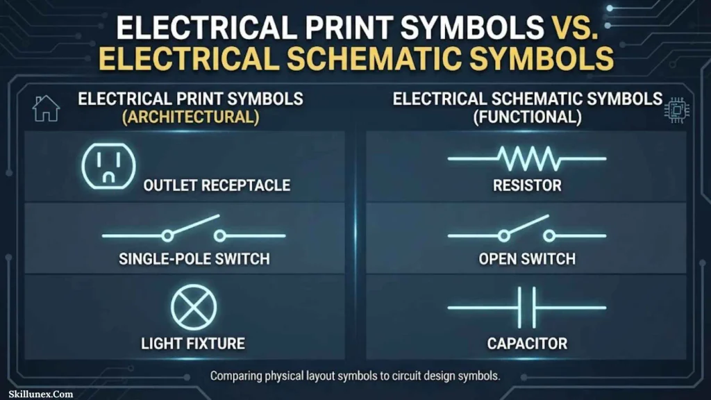
The terms electrical print, electrical drawing, electrical plan, and electrical schematic can overlap, but they aren’t always used to describe exactly the same type of document.
An electrical schematic generally emphasizes how components are electrically connected and how a circuit functions.
An electrical plan may emphasize where devices are physically located within a building or facility.
An electrical wiring diagram may show actual wiring relationships in a more installation-oriented form.
Electrical Plan
An electrical plan often answers:
Where is the device located?
Electrical Schematic
A schematic often answers:
How does the circuit work?
Wiring Diagram
A wiring diagram often answers:
How are the devices and conductors connected?
Understanding this distinction helps you choose the right drawing when you need specific information.
Electrical Drawing Standards
Electrical symbols are influenced by technical standards and drafting conventions.
Depending on the country, industry, and project, you may encounter standards or practices associated with organizations such as:
- IEC
- IEEE
- ANSI
- NFPA
- ISO
These organizations cover different areas of engineering, electrical safety, technical documentation, and standardization.
However, you shouldn’t assume that one universal symbol set applies to every drawing.
A professional project may specify its own drafting conventions in addition to the applicable standards.
Common Mistakes When Reading Electrical Print Symbols
Learning symbols is easier when you know which mistakes to avoid.
Assuming Every Symbol Is Universal
One of the biggest mistakes is assuming that every electrical symbol looks exactly the same everywhere.
Symbol conventions can vary.
Always check the legend before making an important interpretation.
Ignoring the Drawing Legend
A generic chart can help you learn, but the project’s legend should be your first reference when interpreting a real drawing.
Confusing Physical Location With Electrical Connection
A symbol’s location on a floor plan doesn’t necessarily tell you everything about its circuit connection.
You may need to follow circuit lines, tags, and schedules.
Assuming Crossing Wires Are Connected
Crossing conductors may or may not be electrically connected depending on the drafting convention.
Look for the appropriate connection indication.
Looking at Symbols Without Labels
A symbol may identify a component type, while the label provides its unique identity.
For example, two relay symbols might look similar but have different reference numbers and perform different functions.
Ignoring Drawing Notes
Notes can contain critical information about installation requirements, equipment, circuit identification, or special conditions.
Always review the notes before reaching a final interpretation.
How to Read an Electrical Print Step by Step
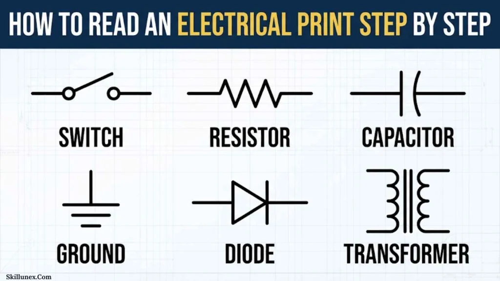
If you’re learning electrical drawings, you can use this process.
Find the Drawing Title
Start by identifying what type of drawing you’re looking at.
It might be a:
- Lighting plan
- Power plan
- Wiring diagram
- Control schematic
- Single-line diagram
- Panel drawing
- Equipment schematic
Check the Legend
Find the symbol legend and review the symbols used on that particular drawing.
Identify the Power Source
Locate the utility connection, transformer, battery, generator, power supply, or other source.
Find Protection
Look for circuit breakers, fuses, overload devices, and other protective equipment.
Follow the Circuit
Trace the conductors from the source toward the load.
Don’t jump randomly around the drawing. Follow the circuit logically.
Identify Control Devices
Find switches, relays, contactors, sensors, PLC components, and other control devices.
Identify the Load
Determine what the circuit ultimately operates.
It could be a light, motor, heater, solenoid, appliance, or electronic circuit.
Check Labels and Schedules
Compare device tags with panel schedules, equipment schedules, wire numbers, and other related drawings.
Review Notes
Finally, read the drawing notes and specifications for information that isn’t communicated through symbols alone.
Electrical Print Symbols Quick Reference Chart
| Symbol Type | Meaning | Common Application |
| Switch | Opens/closes a circuit | Lighting/control |
| Lamp | Light source | Lighting |
| Receptacle | Power connection | Buildings |
| Ground | Grounding connection | Safety/system reference |
| Fuse | Overcurrent protection | Power/control |
| Circuit breaker | Protective switching device | Distribution |
| Transformer | Voltage conversion/isolation | Power/control |
| Motor | Mechanical load | Industrial systems |
| Resistor | Limits current | Electronic/control |
| Capacitor | Stores electrical energy | Power/electronics |
| Inductor | Stores magnetic energy | Filters/power |
| Diode | One-direction semiconductor device | Electronics |
| LED | Light-emitting diode | Indicators/lighting |
| Relay | Electrical control | Automation |
| Contactor | Power switching | Motors/loads |
| Battery | DC source | Control/portable systems |
| Generator | Electrical source | Power generation |
| Ammeter | Current measurement | Testing/metering |
| Voltmeter | Voltage measurement | Testing/metering |
| Terminal block | Wiring connection point | Panels |
| Sensor | Detects physical conditions | Automation |
Frequently Asked Questions
What is the most important electrical symbol to learn first?
If you’re a beginner, start with basic symbols for switches, lights, receptacles, circuit breakers, fuses, ground connections, motors, and transformers. These appear frequently in many types of electrical drawings.
Are electrical print symbols universal?
Not completely. Many symbols are standardized or widely recognized, but conventions can vary between standards, industries, countries, software systems, and individual projects. You should always check the drawing legend.
What is the difference between an electrical plan and a schematic?
An electrical plan generally emphasizes the physical location of electrical devices, while a schematic focuses more on electrical relationships and circuit operation. A wiring diagram may provide more detailed connection information.
How do I read electrical print symbols?
Start with the drawing title and legend. Then identify the power source, protection devices, control components, conductors, and final load. Follow the circuit logically and use labels and schedules to confirm your interpretation.
What does a ground symbol mean on an electrical drawing?
A ground symbol indicates a grounding or earth-related connection, but the exact purpose depends on the drawing. Different ground conventions can represent protective earth, chassis ground, signal ground, or other grounding functions.
What do lines mean on an electrical drawing?
Lines generally represent conductors, connections, or functional relationships depending on the drawing type. You should use the drawing’s conventions to determine whether crossing lines are connected.
Why are electrical symbols important?
Electrical symbols make technical drawings easier to read and communicate. They help electricians, engineers, technicians, designers, and other professionals identify components and understand electrical systems.
Conclusion
Electrical print symbols make complex electrical information easier to understand by replacing lengthy descriptions with recognizable graphical representations. Once you learn the basic symbols for switches, receptacles, lights, breakers, fuses, transformers, motors, relays, contactors, grounding, and electronic components, you can begin reading many electrical drawings with much more confidence.
If you’re learning how to read electrical prints, don’t try to memorize every symbol immediately. Start with the common symbols, learn what each component does, and then practice tracing complete circuits from the power source to the load.
Most importantly, always check the drawing legend, notes, labels, schedules, and applicable standards. A symbol chart is useful for learning, but the project documentation should guide your interpretation of a real electrical drawing.

Caleb Thornton
I’m Caleb Thornton, a researcher and content writer who loves exploring fascinating subjects and sharing what I learn with readers. My interests include natural places, lakes, symbols, culture, history, and the stories that make ordinary topics more meaningful.
When I write an article, I try to go beyond a basic answer. I look for useful facts, relevant context, and details that can help readers understand the subject more completely.
My purpose is simple: I want every article I contribute to provide genuine value, satisfy the reader’s curiosity, and make discovering new information enjoyable.
## Books by Caleb Thornton
* Symbols & Meanings: Exploring the Signs We See Every Day
* Lakes of the World: Nature, Beauty & Exploration