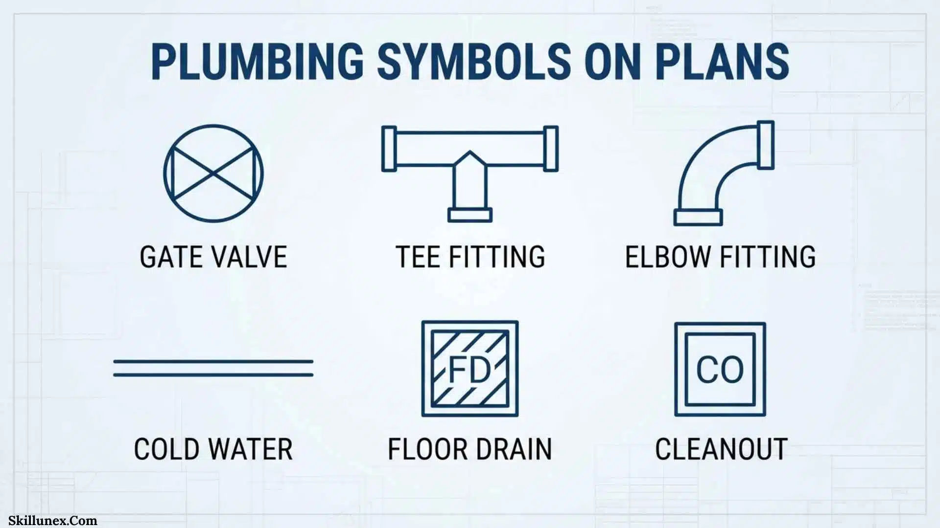
Understanding plumbing symbols on plans is essential for plumbers, contractors, architects, engineers, construction workers, and anyone who needs to interpret plumbing drawings. These symbols provide a simple visual language for showing fixtures, pipes, valves, drains, vents, equipment, and other parts of a plumbing system.
A plumbing plan can initially look complicated because it may contain numerous lines, abbreviations, numbers, tags, and symbols. However, once you understand what these elements represent and learn how to use the drawing legend, reading a plumbing plan becomes much easier.
This guide explains the most common plumbing symbols on plans, their meanings, important plumbing abbreviations, pipe and valve symbols, drainage and vent systems, and the correct way to read a plumbing drawing.
What Are Plumbing Symbols on Plans?
Plumbing symbols on plans are graphical representations used on construction drawings to identify different plumbing fixtures, pipes, valves, drains, vents, equipment, and connections.
Instead of drawing every plumbing component exactly as it will appear after installation, designers use simplified symbols. These symbols save space and allow technical information to be communicated clearly.
A plumbing drawing may contain symbols for:
- Toilets and water closets
- Lavatories and sinks
- Bathtubs and showers
- Urinals
- Floor drains
- Cleanouts
- Water heaters
- Pumps
- Valves
- Water supply pipes
- Sanitary drainage pipes
- Vent pipes
- Storm drainage
- Specialized plumbing equipment
The exact appearance of a symbol can vary between projects, drafting standards, engineering companies, and jurisdictions. For that reason, the plumbing legend on the specific drawing should always be checked before interpreting an unfamiliar symbol.
Why Are Plumbing Symbols Important?
Plumbing drawings need to communicate a large amount of information without becoming difficult to read. Symbols make this possible by giving each component a recognizable graphical representation.
Communicating Fixture Locations
Plumbing symbols show where fixtures such as toilets, sinks, showers, and floor drains are positioned.
They can also indicate the orientation of a fixture and, depending on the level of detail, its connection points.
Showing Pipe Connections
Symbols help show how fixtures connect to water-supply, drainage, and vent systems.
By following the lines connected to a fixture, a plumber or contractor can understand where water comes from and where wastewater is discharged.
Improving Construction Coordination
Plumbing drawings are coordinated with architectural, structural, electrical, and mechanical drawings.
Clear plumbing symbols help different construction teams understand where pipes, fixtures, valves, and equipment need to be installed.
Common Plumbing Symbols on Plans
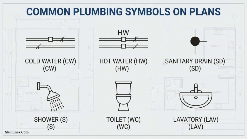
There are many plumbing symbols used in construction drawings. They can generally be divided into fixture symbols, piping symbols, valve symbols, drainage symbols, equipment symbols, and other technical references.
Toilet or Water Closet Symbol
A toilet is commonly identified as a water closet, abbreviated as WC.
The symbol generally represents the fixture as viewed from above. It shows the toilet’s location and orientation within the bathroom.
The drawing may also indicate its connection to the sanitary drainage system and its water-supply connection.
When reviewing a toilet symbol, check:
- Fixture location
- Fixture orientation
- Water-supply connection
- Drain connection
- Fixture tag
- Required clearances
Lavatory Symbol
A lavatory is a bathroom sink used primarily for handwashing.
On a plumbing plan, it may appear as an oval, rectangle, or simplified basin shape. The abbreviation LAV is commonly used.
The plan may show the fixture’s hot-water, cold-water, and waste connections.
Kitchen Sink Symbol
A kitchen sink is usually represented by a rectangular basin, sometimes divided into two compartments.
Depending on the drawing, it may identify:
- Sink location
- Number of bowls
- Faucet position
- Waste connection
- Hot-water connection
- Cold-water connection
An abbreviation such as KS may be used, although project-specific abbreviations should always be confirmed in the legend.
Bathtub Symbol
A bathtub is usually represented by a long rectangular or curved shape.
The symbol may show the location of the:
- Tub drain
- Overflow
- Faucet
- Shower connection
- Hot-water supply
- Cold-water supply
The exact design of the symbol depends on the drawing standard.
Shower Symbol
A shower is typically represented by a square or rectangular enclosure.
More detailed plans may show the shower drain, showerhead, control valve, and water connections.
Common abbreviations include SH or SHR, although these are not universal.
Urinal Symbol
Urinals are frequently shown on commercial and public restroom plans.
Their symbols are generally smaller than toilet symbols and may show the fixture’s water and drainage connections.
A drawing may identify a urinal with UR or another project-specific abbreviation.
Floor Drain Symbol
A floor drain collects wastewater from a floor surface and is common in bathrooms, utility rooms, mechanical spaces, commercial kitchens, garages, and other areas where water may accumulate.
It is often represented by a small circular or square symbol and may be labeled FD.
The plan may also specify the drain size and the pipe connected to it.
Floor Sink Symbol
A floor sink is a deeper receptor that can receive indirect waste from equipment.
Floor sinks are particularly common in commercial kitchens, food-service areas, and mechanical spaces.
The symbol may resemble a larger floor drain but should be interpreted using the project’s plumbing legend.
Plumbing Pipe Symbols and Line Types
Piping makes up a significant portion of most plumbing plans. Different line types, line weights, labels, or abbreviations may be used to distinguish one plumbing system from another.
Cold-Water Piping
Cold-water piping supplies potable water to plumbing fixtures and equipment.
It is commonly identified with CW, although another abbreviation may be specified by the project.
Pipe-size information is often written next to the line.
Hot-Water Piping
Hot-water piping supplies heated water to fixtures such as showers, lavatories, kitchen sinks, and other equipment.
It may be labeled HW or HWS, depending on the project’s drafting conventions.
Sanitary Drainage Piping
Sanitary drainage piping carries wastewater away from fixtures and toward the building drainage system.
It may be identified using abbreviations such as SAN, SS, or other project-specific terminology.
Because drainage systems generally rely on gravity, plans may also provide information about pipe slope and elevation.
Vent Piping
Vent piping provides air to the drainage system and helps maintain proper pressure and trap-seal protection.
Vent lines may be identified as V or VENT.
Vent systems can become complex in larger buildings because several fixtures may connect to common vent piping.
Storm Drainage Piping
Storm drainage piping carries rainwater collected from roofs and other drainage areas.
A plan may distinguish storm drainage from sanitary drainage through line types, labels, or separate drawings.
Common related symbols include roof drains and area drains.
Plumbing Valve Symbols
Valves control, regulate, isolate, or redirect the flow of water within a plumbing system.
Shutoff Valve
A shutoff valve allows a section of piping or a fixture to be isolated.
This is important for maintenance because a plumber can stop water flow to a particular area without necessarily shutting down the entire building.
Gate Valve
Gate valves are commonly used for isolation.
Their graphical representation varies depending on the drafting standard used on the project.
Ball Valve
Ball valves are commonly used as shutoff valves on water-supply systems.
They may be installed near fixtures, equipment, and branch piping.
Check Valve
A check valve prevents or limits reverse flow through the piping system.
The symbol normally communicates the direction in which flow is permitted.
Pressure-Reducing Valve
A pressure-reducing valve lowers water pressure from the upstream side to an appropriate downstream pressure.
It may be located near a building water-service entrance or another location where pressure needs to be controlled.
Mixing Valve
A mixing valve combines hot and cold water to provide water at a controlled temperature.
It may be associated with showers, domestic hot-water systems, or specialized plumbing applications.
Drainage Symbols on Plumbing Plans
Drainage symbols identify components that collect, convey, or provide access to wastewater or stormwater systems.
Cleanout Symbol
A cleanout provides access to drainage piping for inspection, cleaning, and maintenance.
It is commonly labeled CO or C/O.
Cleanouts may appear at changes in direction, bases of stacks, long drainage runs, or other locations required by the design or applicable codes.
An important consideration is accessibility. A cleanout that becomes permanently inaccessible can make future maintenance difficult.
Roof Drain Symbol
A roof drain collects rainwater from a roof and directs it into the storm drainage system.
It is commonly identified with RD.
A roof drainage design may also include overflow drains or other stormwater components.
Area Drain Symbol
Area drains collect surface water from designated areas.
They can be used around courtyards, paved areas, mechanical spaces, parking areas, and other locations where surface drainage is required.
Trench Drain Symbol
A trench drain is a long, narrow drainage channel designed to collect surface water.
It is commonly used in:
- Garages
- Commercial kitchens
- Shower areas
- Wash-down areas
- Industrial facilities
Plumbing Equipment Symbols
Plumbing plans can contain symbols for equipment in addition to fixtures and piping.
Water Heater Symbol
Water heaters may be shown as circles, rectangles, or other simplified shapes.
The drawing may identify:
- Equipment number
- Capacity
- Fuel type
- Hot-water outlet
- Cold-water inlet
- Drain connection
- Relief-valve connection
- Electrical requirements
Detailed specifications are often provided in an equipment schedule.
Pump Symbols
Pumps may be used to move water or wastewater where gravity drainage or normal water pressure is insufficient.
Examples include:
- Booster pumps
- Sump pumps
- Sewage ejector pumps
- Circulation pumps
The pump symbol is usually accompanied by an equipment tag and may be referenced to a schedule or detail.
Backflow Preventer Symbols
Backflow-prevention devices protect potable water supplies from unwanted reverse flow.
A plan may show a backflow preventer near a water-service connection or another location where protection is required.
Common types and abbreviations depend on the application and project specifications.
Plumbing Abbreviations on Plans
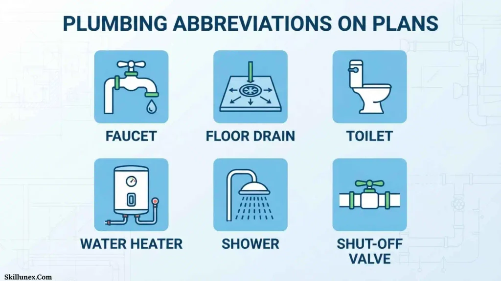
Abbreviations allow designers to communicate technical information without filling the drawing with long descriptions.
Some common plumbing abbreviations include:
| Abbreviation | Common Meaning |
| WC | Water Closet |
| LAV | Lavatory |
| KS | Kitchen Sink |
| FD | Floor Drain |
| FS | Floor Sink |
| CO | Cleanout |
| WH | Water Heater |
| CW | Cold Water |
| HW | Hot Water |
| V | Vent |
| SAN | Sanitary |
| RD | Roof Drain |
| UR | Urinal |
| HB | Hose Bibb |
| PRV | Pressure-Reducing Valve |
| RPZ | Reduced Pressure Zone Backflow Preventer |
These meanings are common industry conventions, but they should not automatically be assumed to apply to every project.
The project’s abbreviation list and plumbing legend should always take priority.
Understanding Pipe Sizes on Plumbing Plans
Pipe sizes are an important part of plumbing drawings.
A pipe may have a size written beside the line, such as 1/2 inch, 3/4 inch, 1 inch, or another size depending on the system.
The apparent thickness of a line on a drawing should not be used to estimate its actual pipe size. Construction drawings are often diagrammatic and may not be drawn to exact scale for every component.
Instead, use:
- Pipe-size labels
- Notes
- Schedules
- Riser diagrams
- Details
- Specifications
Plumbing Tags and References
Plumbing plans often use tags to connect graphical information with schedules and details.
For example, a fixture might be identified as WC-1.
The symbol shows where the fixture is located, while the fixture schedule may provide additional information about its specifications.
Tags may also identify:
- Equipment
- Valves
- Pipe systems
- Details
- Sections
- Riser diagrams
Understanding these references is essential when working with detailed construction documents.
Plumbing Riser Diagrams
A plumbing riser diagram shows the vertical relationships between plumbing systems and different building levels.
This is particularly important in multi-story buildings.
What Does a Riser Diagram Show?
A riser diagram may show:
- Vertical drainage stacks
- Vent stacks
- Water-supply risers
- Branch connections
- Fixtures
- Pipe sizes
- Valves
- Floor levels
- Equipment
A floor plan mainly shows horizontal relationships, while a riser diagram helps explain how the system connects vertically.
Plumbing Isometric Drawings
An isometric plumbing drawing provides a three-dimensional representation of piping.
It can make complicated systems easier to visualize because it shows horizontal and vertical pipe relationships together.
Isometric drawings can help identify:
- Fixture connections
- Vertical stacks
- Horizontal branches
- Vent connections
- Drainage routes
- Pipe elevations
They are especially useful for complicated residential and commercial plumbing installations.
Plumbing Fixture Schedules
A fixture schedule provides detailed information about the plumbing fixtures shown on the plan.
A typical schedule may include:
- Fixture number
- Fixture description
- Manufacturer
- Model
- Quantity
- Water-supply requirements
- Drainage connection
- Special requirements
The floor plan may show only a fixture symbol and tag, while the schedule provides the technical specification.
For this reason, the plan and schedule should be reviewed together.
Plumbing Details and Enlarged Plans
Some plumbing components require more information than can be provided by a simple symbol.
Detailed drawings may be provided for:
- Water heaters
- Backflow preventers
- Floor drains
- Roof drains
- Pumps
- Grease interceptors
- Equipment connections
- Pipe penetrations
- Special fixtures
An enlarged plumbing plan can also provide more information about a particular bathroom, kitchen, mechanical room, or other area.
How to Read Plumbing Symbols on Plans
Learning to read plumbing drawings is easier when you follow a consistent process.
Identify the Drawing Type
Determine whether you are looking at a:
- Plumbing floor plan
- Enlarged plumbing plan
- Riser diagram
- Isometric drawing
- Plumbing detail
- Fixture schedule
- Equipment schedule
This tells you what type of information the drawing is intended to provide.
Find the Plumbing Legend
Locate the legend before interpreting unfamiliar symbols.
Review the fixture symbols, pipe types, valve symbols, abbreviations, and other conventions.
Identify Plumbing Fixtures
Find toilets, sinks, showers, tubs, urinals, floor drains, and other fixtures.
This establishes the basic layout of the plumbing system.
Trace Water Supply Piping
Follow cold- and hot-water lines from their source toward individual fixtures and equipment.
Pay attention to:
- Pipe sizes
- Valves
- Branches
- Equipment
- Directional arrows
- System labels
Trace Drainage Piping
Follow the drainage connection from each fixture toward branch drains, stacks, and the building drainage system.
Look for cleanouts, changes in direction, slopes, and pipe-size changes.
Follow Vent Piping
Identify vent connections and follow them toward vent stacks or other parts of the vent system.
Check Vertical Connections
Use riser diagrams, sections, and details to understand piping that travels between floors.
Review Notes and Schedules
Finally, review all relevant notes, fixture schedules, equipment schedules, specifications, and details.
Important installation requirements may not be represented by symbols alone.
Residential Plumbing Symbols vs. Commercial Plumbing Symbols
Residential and commercial plumbing plans use many of the same basic symbols, but their complexity can be very different.
Residential Plumbing Plans
A residential plumbing plan may include:
- Toilets
- Lavatories
- Kitchen sinks
- Showers
- Bathtubs
- Washing machines
- Water heaters
- Floor drains
- Hose bibbs
- Cleanouts
Because there are generally fewer fixtures and smaller systems, residential plans can be easier for beginners to understand.
Commercial Plumbing Plans
Commercial plans can contain much more extensive plumbing infrastructure.
They may include:
- Multiple restrooms
- Numerous lavatories
- Urinals
- Commercial kitchen fixtures
- Floor sinks
- Grease interceptors
- Large water heaters
- Pumps
- Backflow preventers
- Multiple drainage stacks
- Storm drainage
- Specialized equipment connections
Commercial drawings therefore require closer attention to legends, schedules, riser diagrams, details, and specifications.
Common Mistakes When Reading Plumbing Plans
Even a familiar drawing can be misunderstood if important information is overlooked.
Assuming Every Symbol Is Universal
Not every plumbing symbol is identical across every project.
Solution: Check the project’s legend before interpreting an unfamiliar symbol.
Ignoring Plumbing Abbreviations
Abbreviations can contain important information about the type of fixture or piping.
Solution: Keep the abbreviation list available while reviewing the drawing.
Looking Only at the Floor Plan
A floor plan may not explain how pipes connect vertically.
Solution: Review riser diagrams, sections, and isometric drawings where applicable.
Ignoring Pipe Sizes
Knowing the route of a pipe is not enough to understand the complete design.
Solution: Check the written pipe-size labels, schedules, notes, and specifications.
Ignoring Flow Direction
Some plumbing systems use arrows to show flow direction.
Solution: Check the legend and pay attention to directional arrows.
Treating the Drawing as a Perfectly Scaled Picture

Technical drawings may be diagrammatic rather than perfectly scaled representations of every pipe.
Solution: Use written dimensions, labels, schedules, and details instead of estimating from the visual thickness of lines.
Forgetting Maintenance Access
Valves, cleanouts, and certain equipment require access for maintenance.
Solution: Check that these components remain accessible after construction.
Tips for Beginners Learning Plumbing Symbols
You do not need to memorize every plumbing symbol immediately.
Start with the most frequently encountered components.
Learn Common Fixtures First
Focus on:
- Toilet
- Lavatory
- Kitchen sink
- Shower
- Bathtub
- Urinal
- Floor drain
Learn the Main Pipe Systems
Next, understand:
- Cold water
- Hot water
- Sanitary drainage
- Vent
- Storm drainage
Learn Important Components
Then study:
- Valves
- Cleanouts
- Water heaters
- Pumps
- Backflow preventers
Learn Drawing References
Finally, become familiar with:
- Pipe sizes
- Fixture tags
- Equipment tags
- Arrows
- Elevations
- Details
- Schedules
- Riser diagrams
This step-by-step approach makes complex plumbing drawings much easier to understand.
Frequently Asked Questions About Plumbing Symbols on Plans
What are plumbing symbols on plans?
Plumbing symbols on plans are graphical representations of plumbing fixtures, pipes, valves, drains, vents, equipment, and other components used in construction drawings.
Are plumbing symbols universal?
No. Many symbols follow common conventions, but their appearance can vary between projects, companies, drafting standards, and jurisdictions. The project-specific plumbing legend should always be checked.
What does WC mean on a plumbing plan?
WC commonly means water closet, which is the technical term commonly used for a toilet fixture.
What does FD mean on a plumbing plan?
FD commonly means floor drain.
What does CO mean on a plumbing plan?
CO commonly means cleanout, which provides access to drainage piping for maintenance and cleaning.
What does CW mean on a plumbing plan?
CW commonly refers to cold-water piping.
What does HW mean on a plumbing plan?
HW commonly refers to hot-water piping.
What does SAN mean on a plumbing plan?
SAN commonly refers to sanitary drainage piping, although the exact terminology may vary by project.
What does V mean on a plumbing plan?
V commonly refers to a vent or vent piping.
Why are arrows used on plumbing drawings?
Arrows may indicate the direction of flow or another directional relationship. Their exact meaning should be confirmed using the drawing legend.
What is a plumbing riser diagram?
A plumbing riser diagram shows the vertical relationships between plumbing pipes, fixtures, and systems, particularly between different floors of a building.
Can someone without plumbing experience read a plumbing plan?
Yes. Basic plumbing drawings can be learned by becoming familiar with common symbols, abbreviations, pipe types, and drawing conventions. Complex commercial systems, however, require more technical knowledge and careful review of applicable codes, specifications, and engineering documents.
Why is the plumbing legend important?
The plumbing legend explains the symbols, abbreviations, and line types used on a particular drawing. Since conventions can vary, the legend is the most reliable reference for understanding an unfamiliar symbol.
Conclusion
Understanding plumbing symbols on plans is a fundamental skill for anyone involved in construction, plumbing design, installation, inspection, or estimating.
The symbols provide a visual language for communicating the location and function of fixtures, pipes, valves, drains, vents, equipment, and other plumbing components. However, symbols are only one part of a complete plumbing drawing.
To properly interpret a plan, you should also understand plumbing abbreviations, pipe sizes, line types, fixture and equipment tags, drainage systems, vent systems, riser diagrams, schedules, details, and project notes.
Most importantly, never assume that every plumbing symbol has exactly the same meaning on every drawing. Always refer to the project’s plumbing legend and supporting documentation before making an installation or design decision.
With practice, you can learn to trace water-supply, drainage, and vent systems and understand how the different components work together. If you are reviewing a residential bathroom plan or a complex commercial plumbing system, a solid understanding of plumbing symbols makes technical drawings significantly easier to read and interpret.

Isla Kensington
I’m Isla Kensington, a writer with a passion for research, culture, nature, and the fascinating meanings behind everyday things. I enjoy taking topics that may seem simple at first and discovering the history, facts, and ideas that make them more interesting.
I write with readers in mind. My aim is to provide clear explanations, useful information, and interesting details without making a topic unnecessarily complicated.
I believe learning should feel like discovering something rather than simply reading facts. That philosophy guides the content I create and the topics I choose to explore.
## Books by Isla Kensington
* Symbols Around the World: A Guide to Meaning & Culture
* Nature’s Beautiful Places: Lakes, Landscapes & Natural Treasures