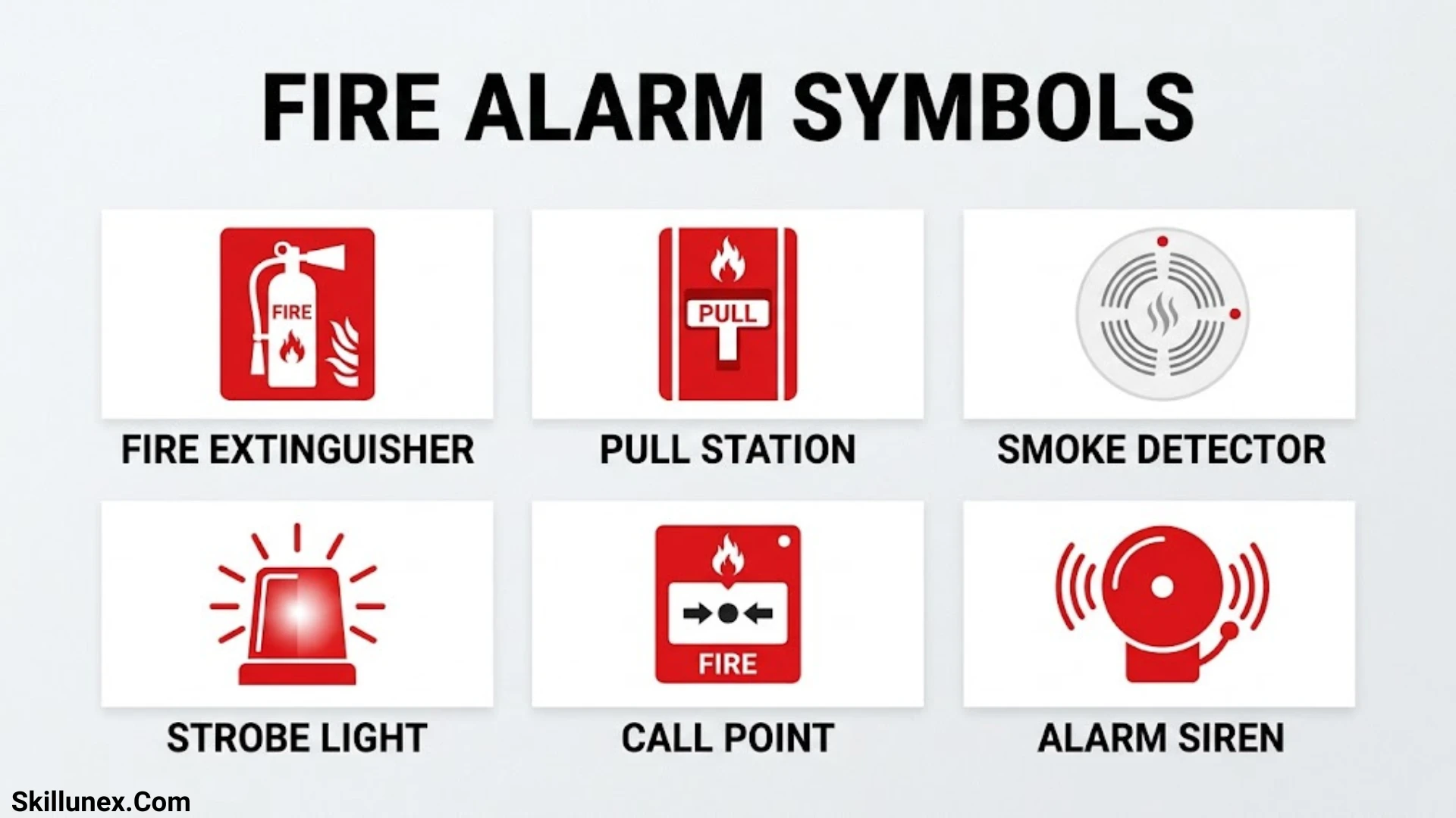
Fire alarm symbols play an important role in keeping you safe during emergencies. These symbols help you identify fire alarms, smoke detectors, heat detectors, emergency exits, fire extinguishers, and other safety equipment. Each symbol has a different meaning, and you should understand them to recognize danger and take the right action at the right time.
When you enter a school, office, hospital, shopping mall, or factory, you may notice different fire alarm symbols on walls, doors, and alarm control panels. I want you to understand these signs so you can easily identify them and know what to do during an emergency. Learning their meanings can help you avoid confusion and respond more confidently.
In this guide, I will explain the most common fire alarm symbols, their meanings, and their uses in simple words. You will also learn how to recognize different warning signs and understand their importance in fire safety systems. By the end, you will have a better understanding of fire alarm symbols and how they help protect you, your family, and others.
What Are Fire Alarm Symbols?
Fire alarm symbols are graphical representations of fire detection and alarm equipment used in technical drawings and building safety documentation. Instead of writing the complete name of every device, engineers use recognizable symbols to show where specific equipment is installed and how different components relate to one another.
These symbols commonly appear in fire alarm layouts, electrical plans, architectural blueprints, fire protection drawings, and life safety documentation.
For example, a fire alarm drawing may contain symbols representing smoke detectors, heat detectors, manual call points, sounders, strobes, fire alarm control panels, and monitoring modules.
Why Are Fire Alarm Symbols Used in Technical Drawings?
Fire alarm symbols help professionals communicate technical information without making drawings unnecessarily complicated. Their consistent use improves the readability of plans and helps installation teams understand the intended system arrangement.
The main purposes include:
- Device identification: Identifying different types of fire detection and alarm equipment.
- Installation planning: Showing the intended locations of detectors, call points, and notification appliances.
- System coordination: Helping electrical engineers, architects, contractors, and fire protection specialists understand the same design.
- Inspection and maintenance: Making it easier to locate individual devices during testing and servicing.
- Emergency planning: Identifying relevant fire safety equipment on building and evacuation plans.
- Technical documentation: Providing a visual record of the installed or proposed fire alarm system.
Where Are Fire Alarm Symbols Commonly Used?
Fire alarm symbols are used in several types of technical and safety documents.
- Electrical drawings: Show fire alarm devices, wiring routes, circuits, and connections.
- Fire protection layouts: Illustrate the locations of detection devices, alarm equipment, and control panels.
- Architectural plans: Help coordinate fire alarm equipment with walls, ceilings, doors, and building spaces.
- Evacuation plans: Identify manual call points, alarm equipment, and other relevant emergency facilities.
- Industrial layouts: Document fire detection equipment in factories, warehouses, and manufacturing facilities.
- As-built drawings: Record the actual locations and arrangements of installed fire alarm equipment.
Common Fire Alarm Symbols and Their Meanings
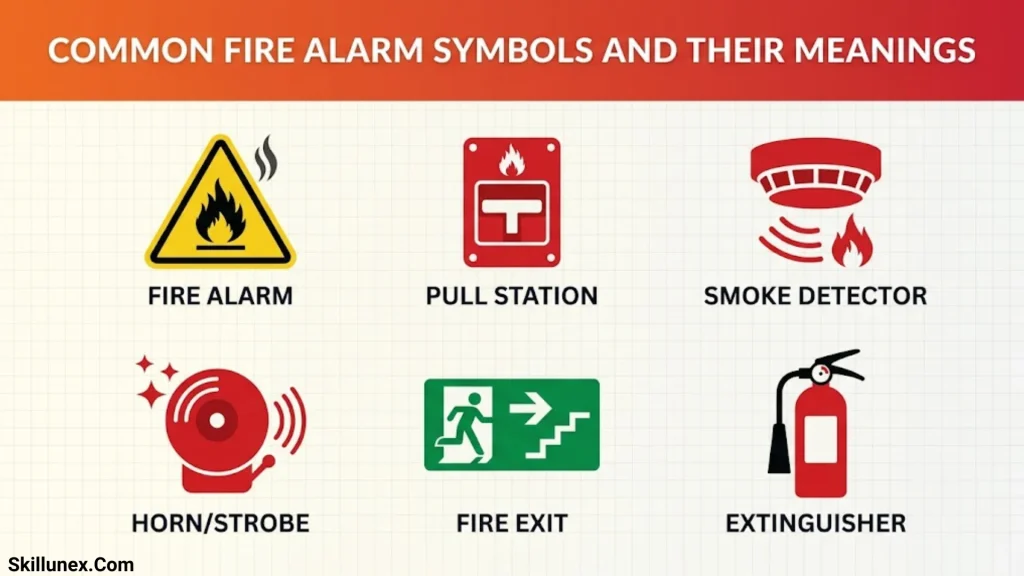
A fire alarm system contains several devices that work together to detect fire conditions, communicate alarm signals, and warn building occupants. Each device is represented by a corresponding symbol in technical drawings.
The exact appearance of a symbol can differ depending on the drawing convention, engineering company, and applicable standard. Therefore, always check the legend included with the drawing.
Smoke Detector Symbol
A smoke detector symbol represents a device designed to detect smoke particles produced by a fire. Smoke detectors are commonly installed in offices, residential buildings, corridors, commercial spaces, and other occupied areas.
There are different technologies used in smoke detection, including photoelectric and ionization sensing. Aspirating smoke detection systems use sampling pipes to draw air into a detection unit.
Common applications:
- Bedrooms and living areas
- Office spaces
- Corridors and circulation areas
- Commercial buildings
- Storage areas where the selected detection technology is suitable
The correct detector type and location depend on the building environment, ceiling configuration, airflow, fire risks, and applicable design requirements.
Heat Detector Symbol
A heat detector symbol identifies a device that responds to a specified temperature or a rapid increase in temperature.
Heat detectors are useful in environments where smoke detectors may experience unwanted alarms because of dust, cooking activities, steam, or other environmental conditions.
Common heat detector types include:
- Fixed-temperature heat detectors: Activate when the surrounding temperature reaches a predetermined threshold.
- Rate-of-rise heat detectors: Respond when the temperature increases rapidly.
- Combination heat detectors: Use more than one temperature-sensing principle.
These devices are commonly considered for kitchens, garages, workshops, and certain industrial environments.
Manual Call Point Symbol
A manual call point symbol represents a manually operated fire alarm activation device. It allows a person who discovers a fire to activate the building’s fire alarm system.
Manual call points are generally installed along escape routes and near exits, staircases, and other accessible locations.
They may be identified by different descriptions, including:
- Manual call point (MCP)
- Manual fire alarm station
- Fire alarm pull station
- Break-glass unit
The exact symbol and abbreviation should be confirmed through the drawing legend.
Fire Alarm Bell Symbol
A fire alarm bell symbol represents an audible notification device that produces a loud sound when the alarm system activates.
Its purpose is to alert occupants to a potential fire emergency and prompt them to follow the building’s evacuation procedures.
Fire alarm bells may be installed in corridors, common areas, offices, industrial buildings, and other occupied spaces.
Fire Alarm Sounder Symbol
A sounder symbol identifies an electronic audible alarm device. Unlike a traditional mechanical bell, an electronic sounder can produce different warning tones and patterns.
Sounders are used to provide audible notification throughout a building. Their location and output should be selected to achieve the required audibility under applicable standards.
Strobe Light Symbol
A strobe light symbol represents a visual notification appliance that produces flashing light during an alarm condition.
Visual notification devices are particularly important in areas where occupants may have hearing difficulties or where background noise makes audible alarms difficult to hear.
They may be installed in offices, public buildings, accessible facilities, and noisy industrial environments.
Sounder and Strobe Symbol
This symbol represents a combined notification appliance that provides both audible and visual warnings.
A sounder-strobe device produces an audible alarm while simultaneously flashing a warning light. Combining these functions helps communicate emergency information to a wider range of building occupants.
Fire Alarm Control Panel Symbol
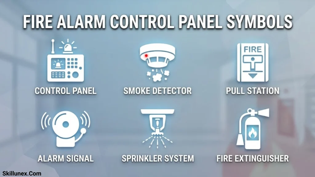
The fire alarm control panel (FACP) symbol identifies the central control equipment of a fire alarm system.
The panel receives information from connected detectors, manual call points, and other initiating devices. It processes these signals and controls notification appliances or other programmed outputs.
Typical fire alarm control panel functions include:
- Receiving signals from detection devices.
- Identifying alarm, supervisory, and trouble conditions.
- Activating programmed notification appliances.
- Monitoring connected circuits and system components.
- Displaying device or zone information.
- Communicating with remote monitoring equipment where provided.
Remote Annunciator Symbol
A remote annunciator symbol represents a secondary display connected to the fire alarm control panel.
It allows authorized personnel to view important system information from another location, such as a reception area, security office, or building entrance.
Depending on the system, it may display alarm locations, trouble conditions, and other operating information.
Duct Smoke Detector Symbol
A duct smoke detector symbol identifies a smoke detection device installed within an HVAC duct or associated air-handling system.
Its purpose is to detect smoke moving through ventilation equipment. Depending on the system design, the detector may initiate an alarm signal or control associated ventilation equipment to help limit smoke distribution.
Duct smoke detectors are commonly used in commercial buildings, hospitals, offices, and large ventilation systems.
Flame Detector Symbol
A flame detector symbol identifies equipment designed to detect the radiation produced by a flame.
Depending on its technology, a flame detector may use ultraviolet (UV), infrared (IR), or combined UV/IR sensing.
These detectors are often considered for high-risk industrial environments, fuel storage facilities, chemical processing areas, and other locations where rapid flame detection is required.
Beam Smoke Detector Symbol
A beam smoke detector symbol represents a detection system that monitors smoke across a large open space using a projected light beam.
The system detects changes in the received light signal caused by smoke entering the beam path.
Beam detectors are commonly considered for:
- Warehouses
- Large halls
- Shopping centers
- Industrial buildings
- High-ceiling spaces
They can provide coverage across large areas, subject to manufacturer instructions and applicable installation requirements.
Aspirating Smoke Detector Symbol
An aspirating smoke detector symbol represents a system that continuously draws air through a network of sampling pipes into a highly sensitive detection unit.
This technology can detect very low concentrations of smoke and is useful in environments where early warning is especially important.
Typical applications include data centers, clean rooms, telecommunications facilities, and specialized industrial spaces.
Fire Alarm System Components and Their Functions

Understanding individual symbols is easier when you know how the complete fire alarm system operates. A typical system contains initiating devices, control equipment, notification appliances, and communication components.
Initiating Devices
Initiating devices detect a fire condition or allow someone to report one manually.
Common initiating devices include:
- Smoke detectors
- Heat detectors
- Flame detectors
- Beam smoke detectors
- Aspirating smoke detectors
- Manual call points
- Waterflow switches
When an initiating device detects a relevant condition, it sends a signal to the fire alarm control panel.
Control and Monitoring Devices
Control and monitoring devices help manage communication between different components of the fire alarm system.
Common examples include:
- Fire alarm control panels
- Remote annunciators
- Input monitoring modules
- Output control modules
- Relay modules
- Isolator modules
- Interface modules
These components allow the system to monitor circuits, receive external signals, and activate programmed equipment.
Notification Appliances
Notification appliances communicate an emergency warning to building occupants.
Examples include:
- Fire alarm bells
- Electronic sounders
- Horns
- Strobe lights
- Voice evacuation speakers
- Combined sounder-strobe units
The type, location, and quantity of notification appliances depend on the building layout, occupancy, environmental conditions, and applicable fire safety requirements.
Power Supply and Backup Equipment
Fire alarm systems require reliable power to operate during normal conditions and emergencies.
Typical power-related components include:
- Main power supply
- Backup batteries
- Power supply monitoring circuits
- Battery charger equipment
- Remote power supplies
Backup power is particularly important because a fire emergency may interrupt the building’s normal electrical supply.
Fire Alarm Symbols Used in Electrical and CAD Drawings

Fire alarm symbols are frequently included in electrical and computer-aided design (CAD) drawings. These drawings help engineers and contractors understand the physical arrangement and electrical connections of the fire alarm system.
Fire Alarm Wiring Symbols
Wiring symbols represent the electrical connections between fire alarm components.
Common drawing elements include:
- Circuit lines: Show the intended electrical connections between devices.
- Addressable loop: Represents the communication circuit connecting addressable system devices.
- Conventional zone circuit: Shows devices connected within a conventional detection zone.
- Power supply connection: Indicates the electrical supply for relevant equipment.
- Earth or grounding symbol: Represents the protective grounding connection where required.
- Terminal connections: Identify connection points for wires and equipment.
- Relay contacts: Represent switching contacts used to control external equipment.
The appearance of these symbols can vary according to the electrical drawing standard and project conventions.
Addressable and Conventional Fire Alarm Symbols
Fire alarm drawings may show two common system architectures.
Addressable Fire Alarm Systems
In an addressable system, individual compatible devices have unique addresses or identifiers. The control panel can identify the specific device reporting an alarm or fault.
Addressable systems are frequently used in larger commercial and industrial buildings because they provide more detailed device identification and system monitoring.
Conventional Fire Alarm Systems
In a conventional system, devices are generally grouped into zones. When an alarm occurs, the control panel identifies the affected zone rather than necessarily identifying the individual detector.
Conventional systems may be suitable for smaller buildings and applications where zone-based identification meets the design requirements.
Fire Alarm Symbols Legend: How to Read It Correctly
A fire alarm symbols legend is a reference section that explains the graphical symbols and abbreviations used in a particular drawing.
It is essential because the same device may be represented differently in drawings prepared by different designers or organizations.
What Information Does a Fire Alarm Legend Include?
A comprehensive fire alarm legend may include:
- Graphical device symbols
- Device names and descriptions
- Equipment abbreviations
- Detector types
- Notification appliance descriptions
- Circuit and wiring conventions
- Control panel identification
- Special installation notes
- Relevant drawing references
For example, a legend may identify the abbreviation SD as a smoke detector, HD as a heat detector, MCP as a manual call point, and FACP as a fire alarm control panel.
These abbreviations are common examples, not universal definitions. Always follow the project specific legend.
Steps for Reading Fire Alarm Symbols on a Floor Plan
Follow these steps when interpreting a fire alarm drawing:
- Locate the drawing legend: Find the section explaining the symbols and abbreviations.
- Identify the equipment: Match the symbol on the floor plan with its description in the legend.
- Check the device location: Determine which room, corridor, or building area contains the equipment.
- Review circuit connections: Follow the lines showing connections between devices and control equipment.
- Check drawing notes: Read any special instructions related to device installation or system operation.
- Review the complete layout: Consider how detectors, notification appliances, and manual call points work together.
- Verify the applicable standards: Confirm that the drawing follows the project’s required codes and design criteria.
Standards and Codes for Fire Alarm Symbols
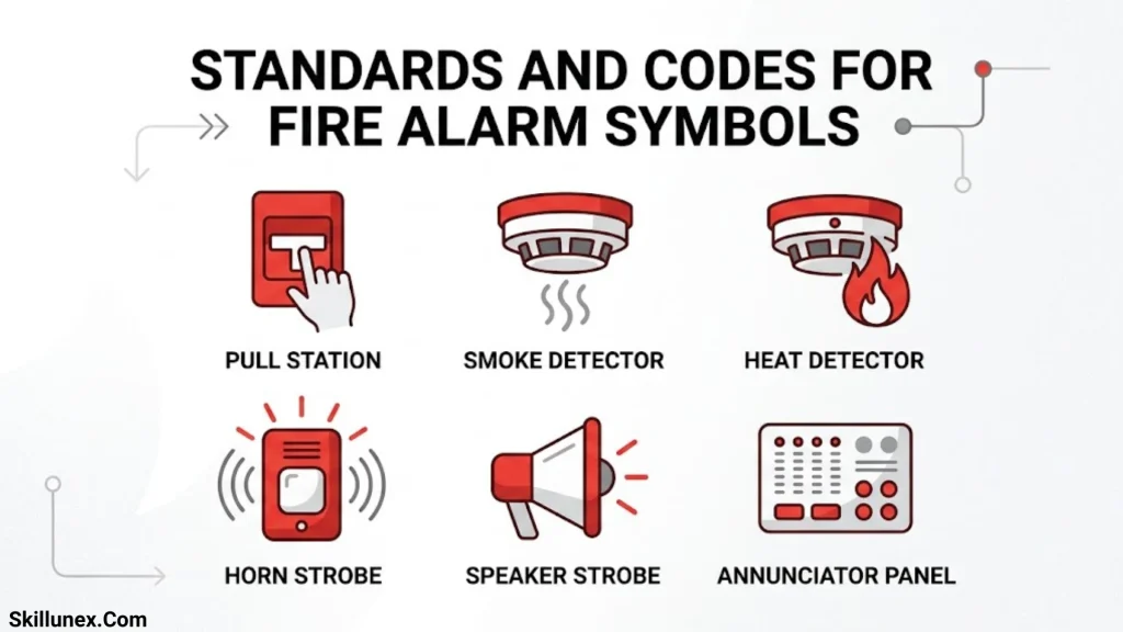
Fire alarm drawings should follow the relevant technical conventions, fire protection standards, and local regulations. However, it is important to understand that a fire alarm system standard and a graphical symbol standard do not necessarily serve the same purpose.
Some widely referenced standards include:
NFPA 72
NFPA 72, the National Fire Alarm and Signaling Code, provides requirements and guidance for fire alarm and signaling systems in the United States and other jurisdictions that adopt it.
It addresses topics such as system installation, performance, inspection, testing, and maintenance.
ISO 7010
ISO 7010 specifies registered safety signs and graphical symbols used to communicate safety information.
It includes fire safety signs, such as those identifying firefighting equipment. It should not be confused with a complete technical symbol library for fire alarm engineering drawings.
BS 5839
BS 5839 is a British Standards series covering fire detection and fire alarm systems.
Different parts address different building types and applications, including non-domestic and domestic premises.
Local Building and Fire Safety Regulations
Local building codes and fire safety regulations may establish additional requirements for system design, equipment selection, installation, and approval.
In Pakistan, project designers should also check the applicable building regulations, fire safety requirements, and approval conditions of the relevant local authority.
How to Create Accurate Fire Alarm Drawings
Accurate fire alarm drawings require more than simply placing symbols on a floor plan. The designer must consider building use, fire risks, detection coverage, evacuation requirements, system architecture, and applicable regulations.
Select the Correct Symbols
Use symbols that clearly represent the intended equipment. Avoid using one symbol for multiple device types unless the project legend specifically explains the distinction.
Prepare a Complete Legend
Include every symbol and abbreviation used in the drawing. A complete legend reduces confusion during installation, inspection, and maintenance.
Position Devices According to Design Requirements
Detector placement should consider room dimensions, ceiling height, structural obstructions, ventilation, environmental conditions, and manufacturer instructions.
Similarly, manual call points and notification appliances should be positioned according to applicable accessibility, audibility, visibility, and installation requirements.
Show Wiring and Circuit Information Clearly
Use appropriate line types and labels to distinguish detection circuits, addressable loops, power supplies, and control connections.
Clearly identify relevant circuit routes and equipment interfaces.
Coordinate With Other Building Systems
Fire alarm drawings should be coordinated with architectural, electrical, mechanical, and other relevant building plans.
For example, smoke detectors and duct detectors may need coordination with HVAC systems, while notification appliances must be considered alongside room layouts and acoustic conditions.
Review and Verify the Drawings
Before finalizing a drawing, check that:
- All devices have been identified.
- Every symbol appears in the legend.
- Circuit connections are understandable.
- Equipment locations are coordinated with the building layout.
- Required system interfaces are documented.
- Applicable codes and approval requirements have been considered.
- The drawing has been reviewed by qualified professionals.
Common Mistakes to Avoid When Using Fire Alarm Symbols
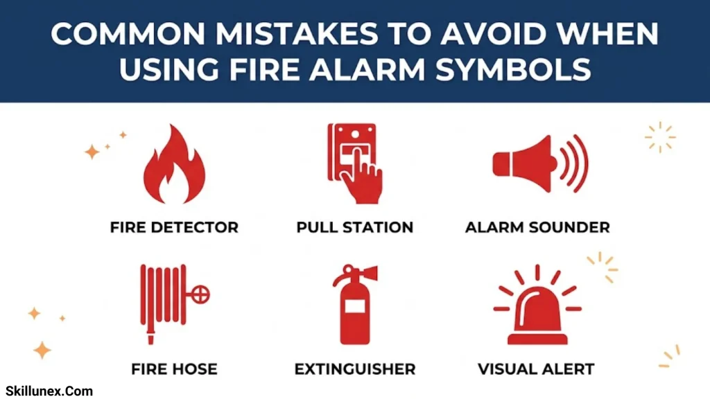
Incorrect symbols and incomplete drawings can create confusion during construction and system maintenance.
Here are some common mistakes to avoid.
Using Symbols Without a Legend
A symbol may have different meanings in different drawing conventions. Always provide a legend that explains the symbols used.
Confusing Smoke Detectors With Heat Detectors
Both devices detect fire-related conditions, but they operate using different sensing principles. Their symbols and descriptions should be clearly distinguished.
Incorrect Device Placement
Simply showing a detector on a floor plan does not establish that its location is technically suitable. Device positioning must follow the relevant design requirements and manufacturer guidance.
Ignoring Wiring and Circuit Details
A drawing that only shows equipment locations may not provide enough information for installation. Include the necessary circuit, connection, and interface details.
Using Outdated Standards
Fire safety requirements can change. Designers should verify the current editions of applicable standards and local regulations before preparing or approving drawings.
Making Drawings Difficult to Read
Overlapping symbols, unclear labels, and inconsistent line types can make a drawing difficult to interpret. Maintain consistent formatting and use suitable drawing scales.
Frequently Asked Questions About Fire Alarm Symbols
What Are the Most Common Fire Alarm Symbols?
Some of the most common fire alarm symbols represent smoke detectors, heat detectors, manual call points, fire alarm bells, sounders, strobe lights, fire alarm control panels, duct smoke detectors, and flame detectors. Their exact graphical appearance depends on the drawing standard and project legend.
What Does SD Mean on a Fire Alarm Drawing?
SD commonly stands for smoke detector. It identifies a device that detects smoke and sends a signal to the fire alarm system. However, abbreviations should always be confirmed through the drawing legend.
What Does MCP Mean in Fire Alarm Systems?
MCP stands for manual call point. It is a manually operated device that allows a person to activate the fire alarm after discovering a fire.
What Is the Symbol for a Fire Alarm Control Panel?
The fire alarm control panel is commonly identified using a rectangular equipment symbol or a labeled panel representation. The exact symbol varies between drawing conventions, so consult the project legend.
Are Fire Alarm Symbols Standardized?
Some fire safety signs and technical drawing conventions are standardized, but not every fire alarm device symbol has one universally used graphical representation. Engineers should follow the relevant project standards and provide a clear legend.
What Is the Difference Between Fire Alarm Symbols and Fire Safety Signs?
Fire alarm symbols are generally used in technical drawings to identify equipment and system components. Fire safety signs communicate safety information to building occupants, such as the location of firefighting equipment or emergency exits.
Which Software Is Used to Create Fire Alarm Drawings?
Common software includes AutoCAD, Revit, and other computer-aided design or building information modeling applications. The choice depends on project requirements and the designer’s workflow.
Why Is a Fire Alarm Symbol Legend Important?
A legend explains the meaning of each symbol and abbreviation used in a drawing. It helps engineers, installers, inspectors, and maintenance personnel interpret the plan accurately.
Conclusion
Fire alarm symbols are a fundamental part of fire protection engineering, electrical design, and building safety documentation. They help represent important equipment, including smoke detectors, heat detectors, manual call points, sounders, strobe lights, control panels, and monitoring devices.
Understanding these symbols makes it easier to interpret fire alarm layouts, coordinate installation work, identify equipment locations, and maintain accurate technical documentation.
However, using symbols correctly requires more than memorizing their meanings. Professionals must also understand system components, wiring arrangements, drawing legends, applicable standards, and device installation requirements.
If you are preparing electrical drawings, reviewing a fire protection plan, or learning about fire detection systems, a clear understanding of fire alarm symbols will help you work with technical drawings more accurately and support effective fire safety planning.

Isla Kensington
I’m Isla Kensington, a writer with a passion for research, culture, nature, and the fascinating meanings behind everyday things. I enjoy taking topics that may seem simple at first and discovering the history, facts, and ideas that make them more interesting.
I write with readers in mind. My aim is to provide clear explanations, useful information, and interesting details without making a topic unnecessarily complicated.
I believe learning should feel like discovering something rather than simply reading facts. That philosophy guides the content I create and the topics I choose to explore.
## Books by Isla Kensington
* Symbols Around the World: A Guide to Meaning & Culture
* Nature’s Beautiful Places: Lakes, Landscapes & Natural Treasures