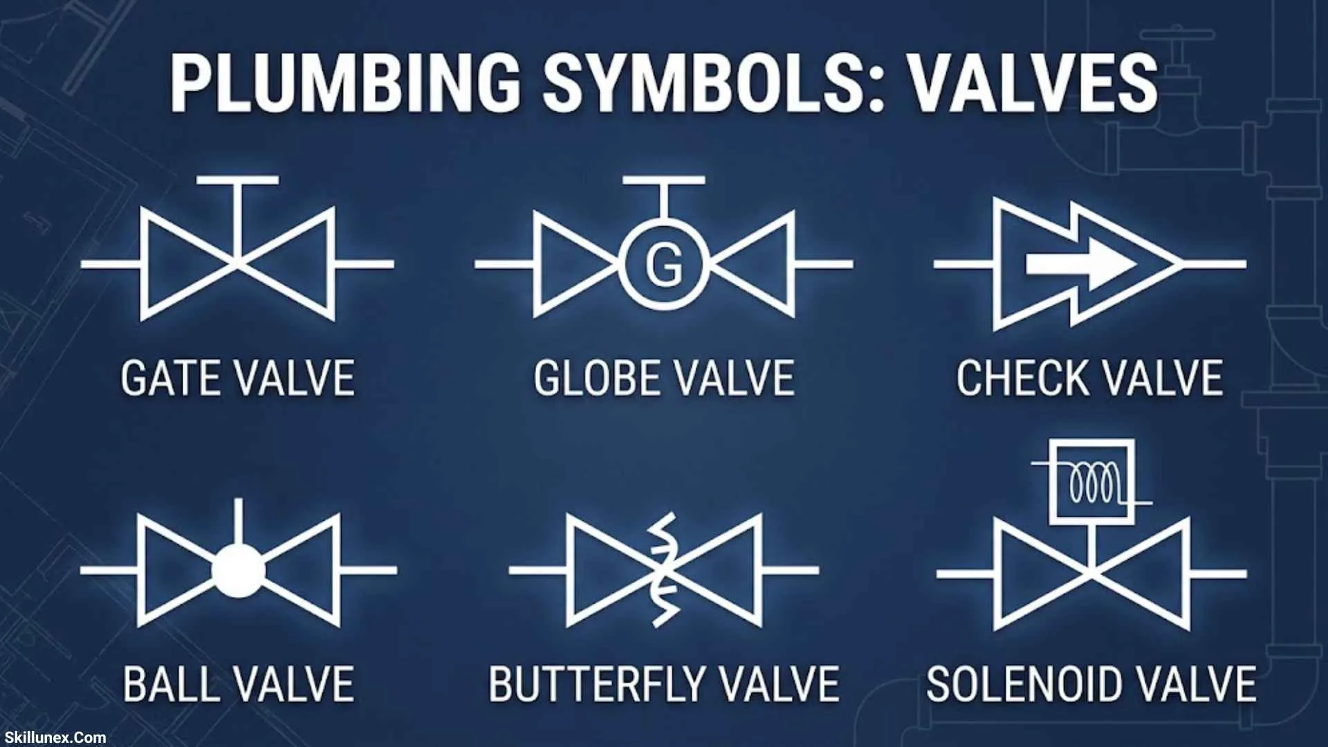
Plumbing symbols valves help you understand how water moves through pipes and how different valves control, stop, or regulate its flow. These symbols are essential for reading plumbing drawings, If you are a plumber, engineering student, or homeowner.
When you first look at a plumbing plan, valve symbols may seem confusing. However, once you understand the meaning of common symbols such as gate valves, ball valves, check valves, and pressure reducing valves, reading technical drawings becomes much easier.
In this guide, I’ll explain the most common plumbing valve symbols, their functions, and their uses in real plumbing systems. You’ll also learn how to read valve abbreviations, recognize differences between similar symbols, and avoid common mistakes when interpreting plumbing diagrams.
Plumbing Symbols Valves: (Quick Answer)
Plumbing symbols valves are graphical representations used in plumbing drawings to show valves that control, stop, or regulate water flow. Common types include gate valves, ball valves, globe valves, check valves, and pressure-reducing valves. These symbols help plumbers and engineers understand pipe systems, identify valve functions, and install equipment correctly.
Quick Facts About Plumbing Symbols Valves
| Aspect | Information |
| Origin | Engineering drawing conventions and industry standards |
| Historical Significance | Improved communication in plumbing and piping design |
| Main Meaning | Controlling, stopping, or regulating fluid flow |
| Common Types | Gate, ball, globe, butterfly, and check valves |
| Technical Importance | Supports installation, maintenance, and troubleshooting |
| Modern Usage | Plumbing plans, mechanical drawings, and piping diagrams |
What Are Plumbing Symbols Valves?
Plumbing valve symbols are simplified graphical representations of valves used in plumbing and engineering drawings. A valve controls the movement of water or another fluid through a pipe. Depending on its design, it can stop flow, regulate pressure, prevent reverse flow, or mix fluids.
Instead of showing every valve in realistic detail, technical drawings use standard or project-specific symbols. These symbols help professionals understand complex pipe networks without filling the drawing with unnecessary details.
Why Plumbing Valve Symbols Matter
Imagine looking at a plumbing plan with pipes connecting bathrooms, kitchens, water heaters, pumps, and storage tanks. Without valve symbols, identifying the location and purpose of each control device would be difficult.
Valve symbols help you identify:
- Water supply isolation points.
- Devices that prevent reverse flow.
- Valves used to regulate pressure.
- Flow-control points in pipe networks.
- Equipment that requires maintenance or protection.
For example, an isolation valve allows a plumber to shut off water to a particular fixture without necessarily interrupting the entire building’s supply.
Plumbing Symbols and P&ID Symbols
Plumbing plans and piping and instrumentation diagrams, commonly called P&IDs, may use different levels of detail.
A plumbing drawing generally shows pipe routes, fixtures, and valve locations. A P&ID may provide additional information about actuators, control signals, pressure regulation, and process equipment.
Standards such as ISO 1219 cover graphical symbols for fluid power systems, while ISO 10628 addresses diagrams for chemical and petrochemical processes. The applicable standard depends on the drawing and its intended use.
Always consult the drawing legend before identifying an unfamiliar symbol.
Types of Plumbing Valve Symbols
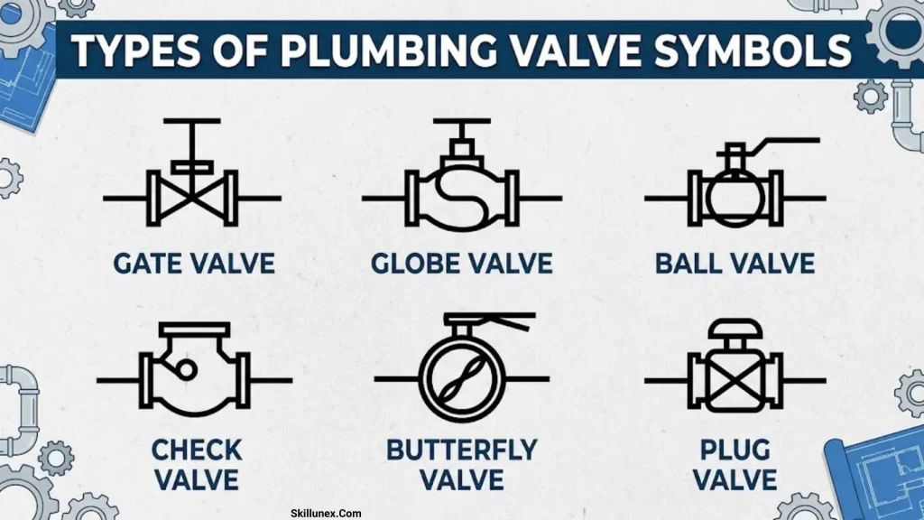
Gate Valve Symbol
Visual description: A simplified gate valve symbol often uses two opposing triangular shapes placed along a pipe line. The exact appearance varies by drafting convention.
Function: A gate valve opens or closes the flow path using a movable gate.
Meaning: It commonly represents an isolation valve used to stop or allow fluid flow.
Applications: Water distribution lines, service connections, and larger pipe systems.
Important detail: Gate valves are generally designed for fully open or fully closed operation rather than continuous flow throttling.
Ball Valve Symbol
Visual description: A ball valve may appear as a simplified valve-body symbol with an additional circle or identifying mark, depending on the drawing standard.
Function: A rotating ball with a hole through its center controls the flow of water.
Meaning: It commonly represents a quick shutoff valve.
Applications: Fixture connections, water heaters, equipment connections, and domestic water supply lines.
Important detail: Many ball valves operate with a quarter-turn handle and provide a tight shutoff when correctly selected and installed.
Globe Valve Symbol
Visual description: A globe valve may use a bow-tie-like body symbol with an additional internal mark.
Function: A movable disc controls the flow through a valve seat.
Meaning: It generally indicates a valve intended for controlled flow adjustment.
Applications: Heating systems, water services, and applications requiring flow regulation.
Important detail: Globe valves typically create more flow resistance than full-bore ball valves.
Butterfly Valve Symbol
Visual description: The symbol may include a simplified disc or line within the valve body.
Function: A rotating disc opens, closes, or regulates flow through the pipe.
Meaning: It represents a compact valve used for isolation or suitable flow-control applications.
Applications: Large water pipes, water treatment plants, and building heating and cooling systems.
Important detail: Butterfly valves are often selected for larger pipe diameters because they can be compact and relatively lightweight.
Check Valve Symbol
Visual description: A check valve symbol may include a directional element, flap, or other mark depending on the valve type and drafting convention.
Function: It permits flow in the intended direction and closes when reverse flow occurs.
Meaning: It represents a non-return function.
Applications: Pump discharge lines and piping systems where reverse flow must be controlled.
Important detail: A check valve is not automatically a substitute for a code-required backflow prevention assembly.
Pressure Reducing Valve Symbol
Visual description: The symbol may combine a basic valve shape with additional regulator or pressure-control markings.
Function: It reduces higher inlet pressure to a controlled lower downstream pressure.
Meaning: It represents a pressure-regulation device.
Applications: Building water supplies, domestic water systems, and equipment requiring lower inlet pressure.
Important detail: A pressure-reducing valve and a pressure-relief valve perform different functions.
Pressure Relief Valve Symbol
Visual description: The symbol may include a valve body with spring or pressure-control markings.
Function: It opens under specified pressure conditions to release fluid and protect equipment.
Meaning: It indicates a pressure-protection device.
Applications: Water heaters, pressure vessels, and other systems requiring pressure relief.
Important detail: Never block or disable a required pressure-relief valve. Its selection and discharge arrangement must comply with applicable codes and equipment instructions.
Solenoid Valve Symbol
Visual description: A solenoid valve symbol often combines a valve symbol with a box or coil representing its electrical actuator.
Function: An electrically energized coil operates or controls the valve mechanism.
Meaning: It represents an electrically operated flow-control device.
Applications: Automatic irrigation, water treatment equipment, and automated plumbing systems.
Important detail: The normal position and operating behavior depend on the specific valve design.
Float Valve Symbol
Visual description: A float valve may be represented by a valve connected to a float mechanism or a simplified liquid-level control symbol.
Function: A float responds to the water level and controls the incoming supply.
Meaning: It represents automatic water-level control.
Applications: Storage tanks, cisterns, and toilet tanks.
Important detail: A float valve does not replace any separate overflow protection required by the system design.
Mixing Valve Symbol
Visual description: A mixing valve may appear as a valve body connected to hot-water and cold-water inlet lines and a mixed outlet.
Function: It combines two fluid streams to produce a controlled mixture.
Meaning: It represents a mixing or temperature-control device.
Applications: Showers, domestic hot-water systems, and installations requiring controlled water temperature.
Important detail: Thermostatic mixing valves can help reduce scalding risks when properly selected, installed, and maintained.
Plumbing Valve Symbols Chart
| Valve Type | Main Function | Common Application |
| Gate valve | Opens or closes flow | Water distribution |
| Ball valve | Provides quick shutoff | Fixture connections |
| Globe valve | Regulates flow | Heating and water systems |
| Butterfly valve | Controls or isolates flow | Large pipework |
| Check valve | Prevents reverse flow | Pump discharge lines |
| Pressure-reducing valve | Reduces downstream pressure | Building water supplies |
| Pressure-relief valve | Releases excess pressure | Water heaters and pressure equipment |
| Solenoid valve | Provides electrical control | Automated systems |
| Float valve | Controls water level | Tanks and cisterns |
| Mixing valve | Combines fluid streams | Hot-water systems |
The chart describes the typical purpose of each valve. For exact graphical representations, use the symbol legend included with the relevant drawing.
How to Read Plumbing Valve Symbols
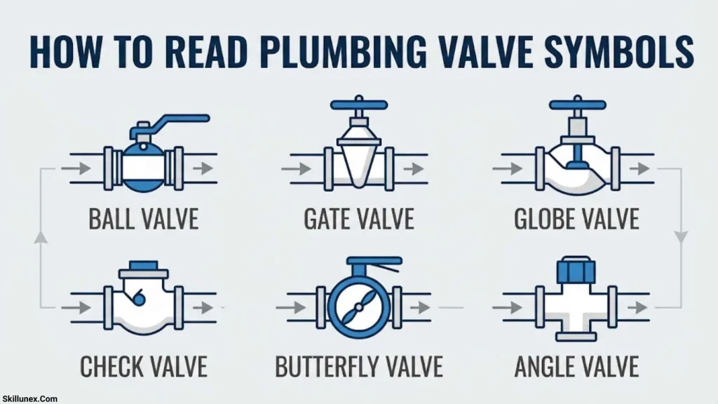
Find the Symbol Legend
Start by locating the drawing legend. It explains the symbols, abbreviations, and line types used on the plumbing plan.
Follow the Pipe Line
Trace the pipe connected to the valve. This helps you understand whether the valve controls a fixture, branch line, tank, pump, or other piece of equipment.
Check the Flow Direction
Look for arrows and inlet or outlet labels. Flow direction is especially important when identifying check valves and directional control devices.
Read Valve Abbreviations
Common abbreviations include BV for ball valve, GV for gate valve, and NRV for non-return valve. However, abbreviations can vary between projects.
Check the Equipment Specifications
A symbol may not show the valve’s size, material, pressure rating, or connection type. Consult the valve schedule and project specifications for these details.
Common Plumbing Valve Abbreviations
| Abbreviation | Common Meaning |
| BV | Ball valve |
| GV | Gate valve |
| GLV | Globe valve |
| CV | Check valve or control valve |
| PRV | Pressure-reducing valve or pressure-relief valve, depending on context |
| NRV | Non-return valve |
| SV | Stop valve, shutoff valve, or solenoid valve, depending on context |
| MV | Mixing valve or motorized valve, depending on context |
| XV | Often an on/off valve designation in process drawings |
Always confirm abbreviations in the drawing legend. For example, PRV can refer to either a pressure-reducing valve or a pressure-relief valve, and these devices have different purposes.
Difference Between Plumbing Valves and Pipe Fittings
Valves control fluid flow, while pipe fittings connect pipes, change direction, or alter pipe size.
| Component | Purpose |
| Elbow | Changes pipe direction |
| Tee | Creates a branch connection |
| Reducer | Changes pipe diameter |
| Coupling | Connects pipe sections |
| Gate valve | Opens or closes a flow path |
| Ball valve | Provides quick flow shutoff |
| Check valve | Prevents reverse flow |
Understanding this difference helps you interpret plumbing drawings accurately and distinguish control devices from connection components.
Plumbing Valve Symbols in Engineering Standards
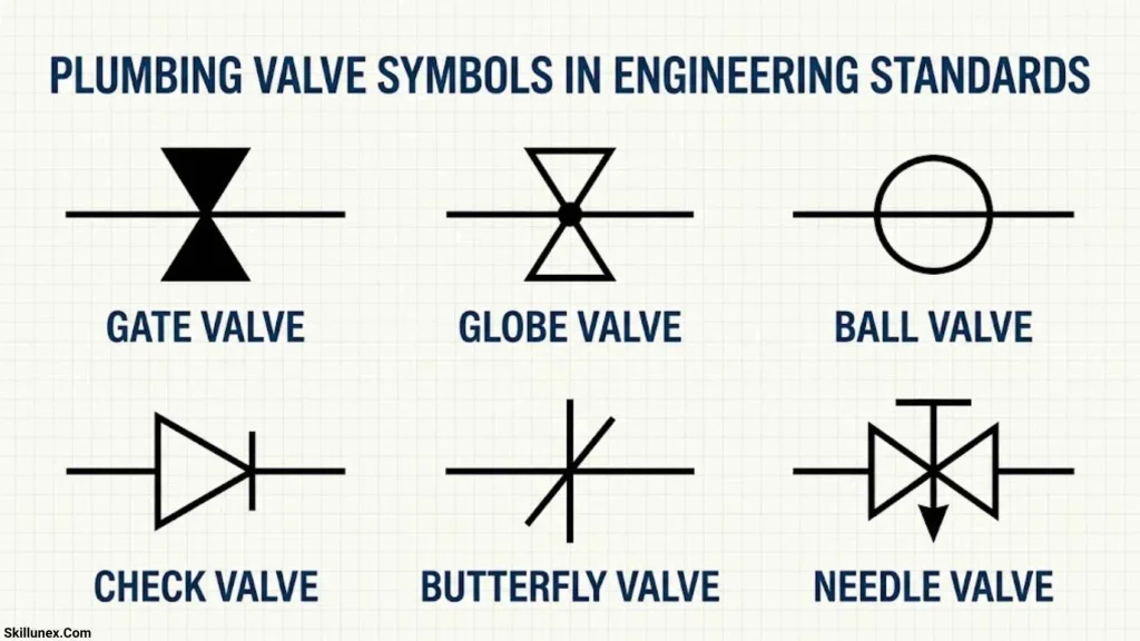
Plumbing valve symbols developed through engineering drawing conventions as water and piping systems became more complex.
Historical Background
Ancient civilizations developed extensive water systems to support irrigation, public water supplies, and sanitation. Ancient Egypt used irrigation channels, while Greek and Roman engineers developed aqueducts and water distribution networks.
Roman infrastructure included aqueducts, public fountains, baths, and different forms of piping. These systems demonstrate the long history of water management, although modern plumbing valve symbols belong to a much later engineering tradition.
Modern Engineering Conventions
As plumbing, mechanical engineering, and industrial processes advanced, engineers needed clear ways to communicate equipment functions through technical drawings.
Modern standards provide graphical conventions for specific fields. Examples include ISO 1219 for fluid power symbols and ISO 10628 for process diagrams used in chemical and petrochemical industries.
However, these standards do not necessarily govern every building plumbing drawing. The project legend and specified standards remain the best references for interpreting a particular valve symbol.
Common Mistakes When Identifying Plumbing Valve Symbols
Assuming All Symbols Are Universal
A symbol used on one drawing may look different on another. Always check the legend before deciding what a mark represents.
Confusing Pressure Reducing and Pressure-Relief Valves
A pressure-reducing valve controls downstream pressure. A pressure-relief valve opens to release fluid under specified pressure conditions. They are not interchangeable.
Ignoring Flow Direction
Check valves and other directional devices must be installed according to their intended flow direction.
Relying Only on Abbreviations
Abbreviations such as CV, SV, and PRV can have more than one meaning. Read the surrounding labels and consult the valve schedule.
Assuming the Drawing Matches the Installed System
Existing plumbing may have been modified after the original plan was created. Confirm actual valve locations before carrying out maintenance or repairs.
Interesting Facts About Plumbing Valve Symbols
- A simple symbol can represent a mechanical device with several internal components.
- Valve symbols help engineers communicate designs without drawing every component realistically.
- Check valves operate automatically in response to flow conditions.
- Ball valves commonly use a quarter-turn mechanism for opening and closing.
- Pressure-reducing valves and pressure-relief valves serve different purposes.
- Detailed P&IDs may include valve actuators, electrical signals, and control relationships.
- A valve symbol does not necessarily provide the valve’s size, material, or pressure rating.
- Accurate plumbing drawings help maintenance teams locate isolation points and understand pipe layouts.
Frequently Asked Questions
What are the most common plumbing valve symbols?
The most common valve types include gate valves, ball valves, globe valves, butterfly valves, check valves, pressure-reducing valves, and pressure-relief valves. Their exact symbols depend on the drawing convention.
How do I identify a valve symbol on a plumbing plan?
Find the symbol legend, inspect the shape, follow the connected pipe, and read nearby abbreviations. Check the valve schedule when you need information about size, material, or pressure rating.
What does PRV mean in plumbing?
PRV commonly means pressure-reducing valve or pressure-relief valve, depending on the drawing convention. Check the legend and equipment specifications to determine which device is intended.
What is the difference between a ball valve and a gate valve?
A ball valve uses a rotating ball with a hole to control flow. A gate valve uses a movable gate that rises or lowers across the passage. Both can provide isolation, but their mechanisms and operating characteristics differ.
What does a check valve symbol mean?
A check valve symbol represents a device designed to permit flow in one direction and prevent or restrict reverse flow. It is commonly used in pump discharge lines and other suitable piping applications.
Where can I find a plumbing valve symbols chart?
Check the plumbing drawing legend, project specifications, relevant engineering standards, or the manufacturer’s technical documentation. These sources help you identify the correct symbol for the specific system.
Conclusion
Plumbing symbols valves make it easier to understand how water flows through pipes and how different valves control pressure, prevent backflow, and shut off water supplies. By learning common symbols such as gate valves, ball valves, globe valves, and check valves, you can read plumbing drawings more confidently and understand the purpose of each component. These symbols are essential for plumbers, engineers, students, and anyone working with plumbing systems.
Understanding valve symbols also helps you avoid confusion when reading technical plans or identifying equipment. Always check the drawing legend, valve abbreviations, and project specifications to confirm the correct meaning. With practice, you can recognize common plumbing valve symbols quickly and understand how they contribute to a safe, efficient, and reliable plumbing system.

I’m Adrian Holloway, a writer and researcher who enjoys exploring the stories, meanings, and interesting facts behind the subjects people search for every day. I’m especially interested in symbols, nature, lakes, places, and cultural topics that help readers understand the world from a different perspective.
I believe useful content should be simple, accurate, and enjoyable to read. When I research a topic, I focus on finding meaningful details and presenting them in a way that makes information easy to understand.
My goal is to create helpful articles that answer real questions while encouraging readers to discover something new with every visit.
Books by Adrian Holloway
The Language of Symbols: Meanings, Stories & Traditions
Hidden Wonders of Nature: Lakes, Landscapes & Discovery