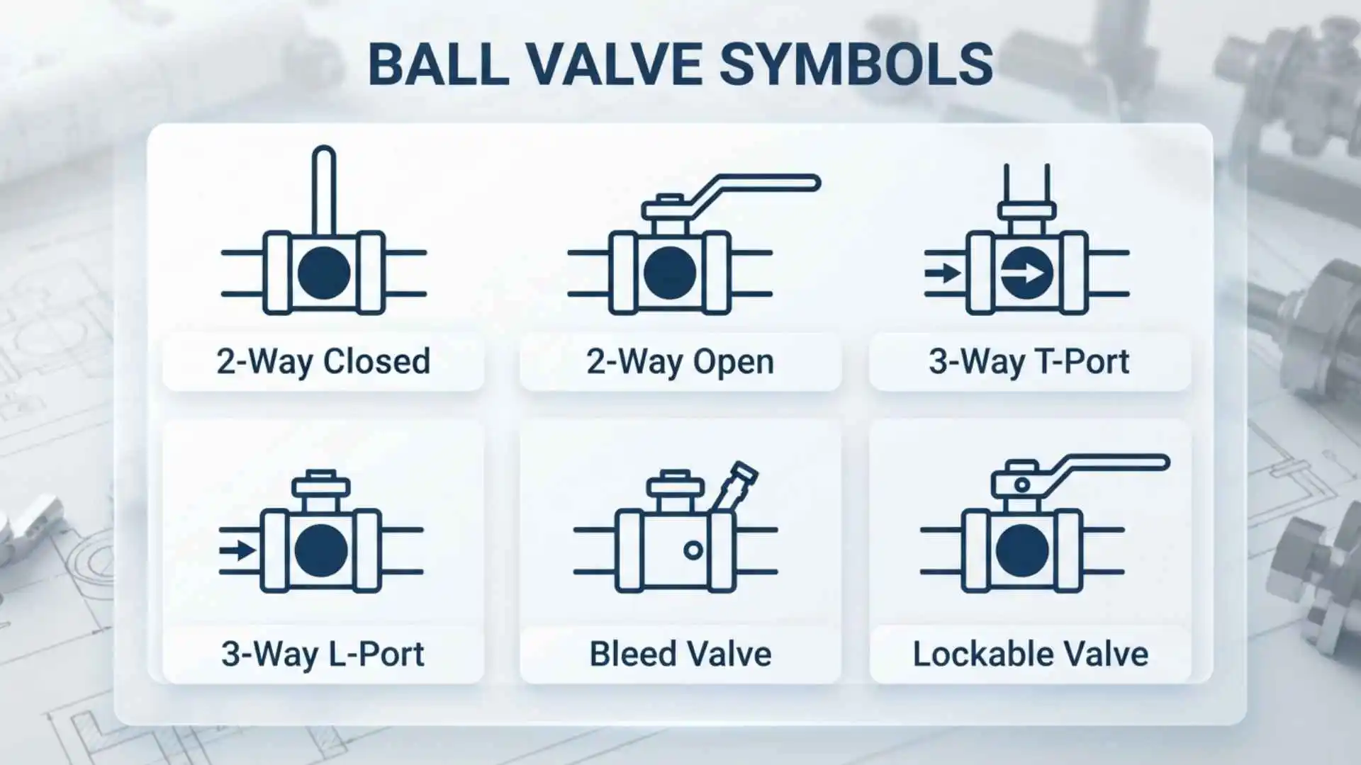
Ball valve symbols are graphical representations used on P&IDs (Piping and Instrumentation Diagrams), piping drawings, process flow diagrams, and other engineering schematics to show where a ball valve is installed and how it functions.
A typical ball valve uses a sphere with a hole through its center to control the flow of liquid or gas. In engineering drawings, however, the actual valve is not usually drawn as a realistic three-dimensional component. Instead, standardized or convention-based symbols are used to communicate the valve’s function quickly.
Understanding ball valve symbols is useful for engineers, technicians, maintenance personnel, operators, students, and anyone who needs to interpret piping and instrumentation drawings.
The important point is that there is not necessarily one identical ball valve symbol used on every drawing. The exact appearance can depend on the applicable drafting standard, project conventions, diagram type, and whether additional information such as actuation or fail position is being shown.
What Is a Ball Valve Symbol?
A ball valve symbol is a simplified graphic used to identify a ball-type shutoff or control valve on an engineering drawing.
What Does a Ball Valve Symbol Represent?
A valve symbol generally communicates function rather than physical appearance. It tells the reader that a valve exists at a particular point in a piping system and may provide additional information about its operation.
Depending on the drawing, a ball valve representation can communicate:
- Valve location
- Valve type
- Flow-path arrangement
- Manual or automatic operation
- Actuator type
- Normally open or normally closed status
- Fail position
- Valve identification or tag number
- Connections to an instrument or control system
The symbol is therefore only one part of the information provided about the valve.
Why Are Ball Valve Symbols Used?
Drawing a realistic ball valve on every process diagram would make engineering drawings difficult to read.
A standardized graphical representation allows a complex piping system to be displayed using simple lines and symbols. Engineers can therefore identify valves, pumps, instruments, fittings, and other equipment without needing a detailed illustration of every component.
This is particularly important on large P&IDs, where hundreds or even thousands of components may appear on a single project.
What Does a Ball Valve Symbol Look Like?
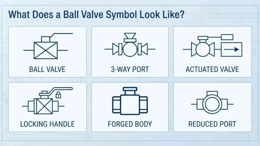
There is no single appearance that should automatically be assumed to apply to every engineering drawing. Many common valve-symbol conventions use a basic valve body placed across the pipe line, with additional graphical elements identifying the valve type or operator.
Basic Ball Valve Representation
In simplified schematics, a ball valve may be represented by a valve body with a circular or spherical element inside it. Depending on the drafting convention, the internal element and line through it can indicate the ball and its flow passage.
A simplified conceptual representation might look like:
──────◯──────
However, this should be treated as an illustrative concept rather than a universal standards-compliant symbol. The exact graphical form should always be interpreted according to the legend or symbol standard used on the drawing.
Why the Drawing May Look Different
A ball valve symbol can look different because drawings may follow different standards or conventions, including:
- ISO-based practices
- IEC graphical conventions
- ASME-related drafting practices
- ISA conventions for process and instrumentation diagrams
- Company or project-specific standards
- Manufacturer documentation
This is one of the most important things to remember when reading a valve symbol: do not identify a valve solely from an isolated graphic when the drawing legend is available.
Ball Valve Symbols on P&IDs
P&IDs are among the most common places where engineers encounter ball valve symbols.
How Ball Valves Appear on a P&ID
On a P&ID, the valve is normally positioned directly on the process line. The symbol identifies the valve, while a nearby tag provides additional information.
A typical drawing may contain information such as:
Valve tag → valve type → actuator → control or safety function
For example, a valve might have a tag such as:
XV-101
The exact meaning of the letters depends on the project’s tagging convention. On many projects, XV is used for an on/off valve, but tag conventions are project-specific and should be confirmed from the P&ID legend.
Why the P&ID Legend Matters
The legend is one of the most valuable resources when interpreting a P&ID.
A professional drawing may define:
- Valve symbols
- Instrument symbols
- Line types
- Signal types
- Actuator representations
- Equipment abbreviations
- Valve tag conventions
If a symbol appears unfamiliar, checking the drawing legend is usually more reliable than assuming its meaning from a symbol found online.
Common Types of Ball Valve Symbols
Ball valves can perform different functions, and additional graphical information may distinguish one application from another.
Two-Way Ball Valve Symbol
A two-way ball valve has two ports and is commonly used to start, stop, or isolate flow.
Its basic operating principle is straightforward:
- Ball hole aligned with the pipe → flow is permitted
- Ball rotated approximately 90° → flow is blocked
Two-way ball valves are widely used for isolation in water, compressed air, gas, chemical, and industrial piping systems.
Three-Way Ball Valve Symbol
A three-way ball valve has three ports and can direct flow between different piping paths.
Common arrangements include:
- L-port
- T-port
An L-port configuration can connect one inlet to one of two outlets, while a T-port configuration can provide different flow-routing combinations depending on the ball design and rotation.
Because three-way valves have more possible flow paths, their symbols may include additional graphical information to make the port arrangement clear.
Four-Way Ball Valve Symbol
Four-way ball valves are less common in ordinary process piping but are used in applications requiring more complex flow routing.
The symbol must communicate the relevant connection arrangement because the key feature of a multi-port ball valve is not simply that it is a ball valve—it is how the internal flow paths connect the ports.
Manual Ball Valve Symbols
A manual ball valve is operated directly by a person, usually through a lever, handle, handwheel, or similar mechanism.
How Manual Operation Is Shown
On an engineering drawing, the valve body may be accompanied by a graphical representation of its operator.
The exact representation depends on the drawing convention.
A manual ball valve is generally distinguishable from an automatically actuated valve because it does not have the same actuator representation or instrument connection.
Where Manual Ball Valves Are Used
Manual ball valves are commonly used for:
- Equipment isolation
- Pipeline isolation
- Maintenance shutdowns
- Utility systems
- Water services
- Compressed-air systems
- Gas services
They are particularly useful where frequent automated operation is not required.
Actuated Ball Valve Symbols
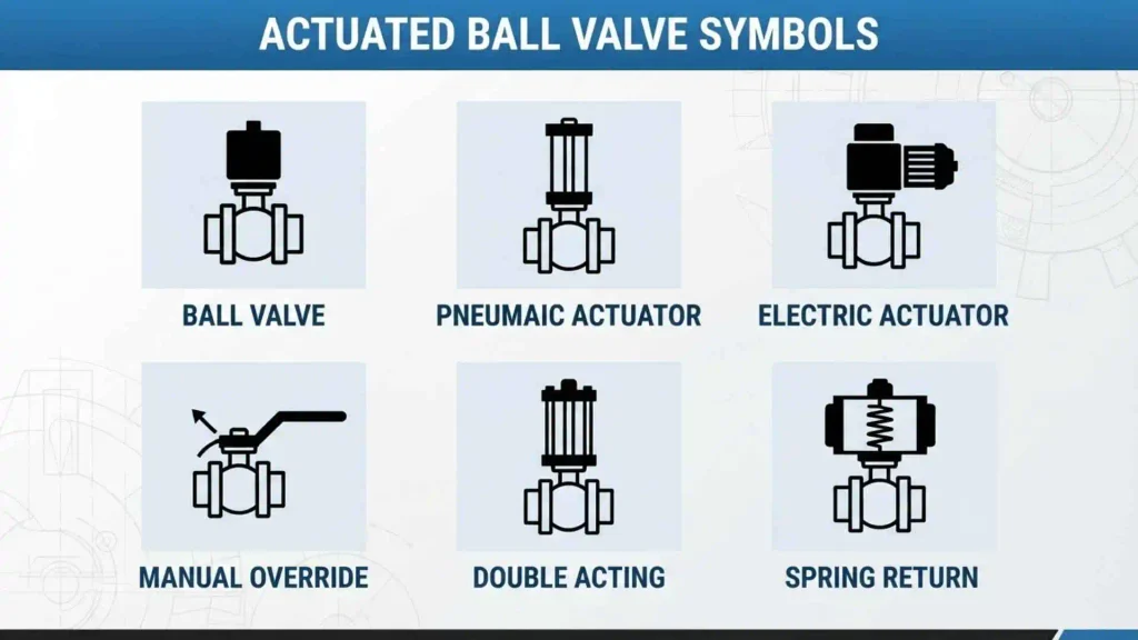
An actuated ball valve uses an external actuator to rotate the ball rather than relying on a person to operate the valve manually.
Pneumatic Ball Valve Symbols
Pneumatic actuators use compressed air to operate the valve.
On P&IDs, the actuator is normally represented separately from the basic valve body so the reader can understand that the valve is automated.
Pneumatic ball valves are common in process industries because they can operate quickly and can be integrated into automated control systems.
Electric Ball Valve Symbols
An electric actuator uses an electric motor or electrically powered mechanism to operate the valve.
Electrical actuation can be useful where:
- Compressed air is unavailable
- Precise positioning is required
- Remote operation is needed
- The process requires automated isolation
The actuator representation on a drawing should be interpreted according to the applicable project or drafting standard.
Normally Open and Normally Closed Ball Valves
One of the most important distinctions on an instrumentation drawing is whether an automated valve is intended to be open or closed under a defined normal condition.
Normally Open Ball Valve
A normally open valve is intended to remain open under its specified normal or de-energized condition, depending on the project’s definition.
This does not necessarily mean the valve is physically open at every moment. It describes the designated normal state used by the system or control philosophy.
Normally Closed Ball Valve
A normally closed valve is intended to remain closed under its specified normal condition.
This can be useful when a process line should remain isolated until a control system or operator deliberately opens the valve.
The exact meaning of “normal” should be checked against the project’s control philosophy because drawing conventions can vary.
Fail-Open and Fail-Closed Ball Valve Symbols
Automated ball valves may also have a specified fail position.
Fail Open
A fail-open valve is designed so that, following a defined actuator or energy failure, the valve moves or remains in the open position.
This can be selected when continued flow is considered safer or operationally preferable.
Fail Closed
A fail-closed valve moves or remains closed following the defined failure condition.
Fail-closed operation is often selected when stopping the flow is the safer response.
The fail action depends on the actuator, accessories, process requirements, and safety philosophy. It should not be inferred solely from the basic ball valve body symbol.
Ball Valve Symbols vs. Other Valve Symbols
Recognizing the difference between valve types is essential when reading engineering drawings.
Ball Valve vs. Gate Valve Symbol
Both ball and gate valves can be used for isolation, but they have different internal designs and operating characteristics.
A ball valve uses a rotating ball with a bore.
A gate valve uses a gate that moves into or out of the flow path.
Their graphical symbols may look similar in highly simplified drawings, which is why the drawing legend and valve designation are important.
Ball Valve vs. Globe Valve Symbol
A globe valve uses a movable closure element that operates against a seat.
Globe valves are commonly associated with throttling and flow regulation, while ball valves are frequently selected for rapid isolation and on/off service.
Again, the exact graphical distinction depends on the applicable symbol standard.
Ball Valve vs. Butterfly Valve Symbol
A butterfly valve uses a rotating disc mounted inside the pipe.
Ball and butterfly valves can both be quarter-turn valves, but their symbols represent different valve constructions.
A butterfly valve symbol generally includes graphical elements intended to represent the disc, while a ball valve representation uses the convention for a spherical closure element.
How to Read a Ball Valve Symbol on an Engineering Drawing
Identifying a symbol is only the first step. A P&ID often contains several pieces of information that must be read together.
Step 1: Find the Valve on the Pipe
Start by locating the valve symbol on the process or utility line.
The pipe line tells you where the valve is installed within the system.
Step 2: Check the Valve Symbol
Look at the graphical representation and compare it with the drawing legend.
Do not rely solely on memory, especially when working with unfamiliar standards.
Step 3: Read the Valve Tag
Find the alphanumeric tag next to the valve.
The tag allows the valve to be identified in:
- Valve schedules
- Datasheets
- Procurement documents
- Maintenance records
- Control-system documentation
Step 4: Identify the Actuator
Check whether the valve has a manual operator, pneumatic actuator, electric actuator, hydraulic actuator, or another operating mechanism.
Step 5: Look for Instrument Connections
Automated valves may have connections to:
- Solenoid valves
- Positioners
- Limit switches
- Control systems
- Instrument air
- Electrical signals
These details help explain how the valve operates within the process.
Step 6: Check the Control Philosophy
For an automated valve, determine its normal state and failure action.
A complete interpretation may require looking beyond the P&ID to documents such as:
- Control narratives
- Cause-and-effect diagrams
- Instrument datasheets
- Valve datasheets
- Functional specifications
Ball Valve Symbols and Flow Direction
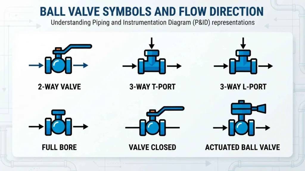
A ball valve is generally capable of controlling flow in either direction unless the specific design or service imposes directional requirements.
Does a Ball Valve Symbol Show Flow Direction?
The valve symbol itself does not necessarily establish the direction of process flow.
Flow direction is usually communicated through an arrow on the piping line or through the relevant process drawing convention.
This distinction is important because readers sometimes assume the orientation of a valve symbol automatically indicates flow direction.
Three-Way Ball Valves Are Different
For a three-way ball valve, the symbol or associated documentation must communicate the available flow paths.
The correct interpretation depends on the valve’s internal ball configuration and its operating position.
For complex valves, the manufacturer’s flow-path diagram can be more informative than the basic P&ID symbol.
Common Mistakes When Reading Ball Valve Symbols
Even experienced readers can misinterpret symbols when they overlook the information surrounding them.
Assuming There Is One Universal Ball Valve Symbol
Different standards and companies may use different graphical conventions.
Better practice: always check the project legend or governing standard.
Confusing Valve Type With Valve Function
A ball valve is a valve construction/type. It does not automatically tell you whether the valve is:
- Manual
- Automatic
- Normally open
- Normally closed
- Fail open
- Fail closed
- Used for isolation
- Used for control
Those characteristics require additional information.
Ignoring the Valve Tag
The symbol identifies the component graphically, but the tag connects it to the project’s documentation.
Ignoring the tag can make it difficult to find the corresponding datasheet, specification, or maintenance record.
Assuming the Symbol Shows the Real Valve Shape
Engineering symbols are simplified representations.
A real ball valve can have different body designs, end connections, materials, actuator arrangements, and sizes while still being represented by the same basic symbol.
Ball Valve Symbols in Different Engineering Drawings
The same physical valve may be represented differently depending on the type of document.
P&ID
A P&ID provides detailed information about process equipment, valves, instruments, control functions, and piping relationships.
This is one of the most important drawings for understanding how a ball valve interacts with the process.
Process Flow Diagram
A PFD is generally less detailed than a P&ID.
It focuses on major equipment and process flow rather than providing the complete valve and instrumentation detail found on a P&ID.
Piping Isometric
A piping isometric focuses more heavily on the physical arrangement and construction of piping.
A valve may be shown in a more recognizable physical form or through a project-specific drafting representation.
Instrumentation Documentation
Instrumentation documents can provide additional information about automated ball valves, including actuator type, control signals, position feedback, and failure behavior.
Ball Valve Symbol Standards and Drawing Conventions
Standards help engineers communicate consistently, but it is important to distinguish between international standards, industry practices, and project-specific conventions.
ISO and IEC Conventions
International standards organizations publish graphical-symbol conventions for diagrams and fluid-power or process-related documentation.
These standards help establish consistent methods for representing components, but the exact symbol applicable to a particular drawing depends on the standard and diagram type being used.
ISA Conventions
ISA standards are widely used in process industries for instrumentation and control documentation.
They are particularly relevant when a ball valve is part of an automated control loop and the drawing needs to communicate instrumentation and control functions.
ASME and Project Standards
Engineering projects may also reference ASME publications, company drafting standards, client specifications, or other applicable requirements.
For this reason, the legend on the actual engineering drawing should always take priority when identifying a symbol.
Why Ball Valve Symbols Matter in Industry
A correctly interpreted valve symbol can provide valuable information before anyone physically examines the equipment.
Design and Engineering
Engineers use symbols to design and review process systems.
They can determine where valves are installed and how they interact with equipment and piping.
Operations
Operators can use P&IDs to understand the location and function of valves within a process.
Maintenance
Maintenance personnel can use valve tags and drawings to identify equipment and trace it back to specifications and records.
Safety
Valve symbols can also support safety reviews by showing isolation points, automated shutdown valves, and connections to control systems.
This is particularly important during activities such as process hazard analysis, maintenance planning, commissioning, and emergency response.
Frequently Asked Questions
What is the symbol for a ball valve?
A ball valve is represented by a standardized or project-specific valve graphic that identifies its valve body and closure element. The exact appearance varies by drawing standard and application, so the P&ID legend should be used to confirm the symbol.
How do you identify a ball valve on a P&ID?
Locate the valve graphic on the piping line, compare it with the drawing legend, and then check the valve tag and associated documentation. Additional symbols may identify the actuator, instrumentation, normal state, or failure action.
What does a circle in a ball valve symbol mean?
A circular element may be used in some graphical conventions to represent the ball or closure element, but a circle by itself should not automatically be interpreted as a ball valve. The complete symbol and drawing legend determine its meaning.
What is the difference between a ball valve and a gate valve symbol?
The two valve types use different graphical conventions because their closure mechanisms are different. A ball valve uses a rotating spherical element, while a gate valve uses a gate that moves into or out of the flow path. Always check the applicable symbol legend.
What does a three-way ball valve symbol mean?
A three-way ball valve symbol represents a ball valve with three ports that can route flow between different piping connections. The specific flow paths depend on whether the valve uses an L-port, T-port, or another internal configuration.
What does a ball valve with an actuator symbol mean?
It indicates that the ball valve is operated by an actuator rather than solely by a person. The actuator may be pneumatic, electric, hydraulic, or another type, depending on the drawing.
How is a pneumatic ball valve shown on a P&ID?
A pneumatic ball valve is generally shown as a ball valve symbol with a separate graphical representation identifying its pneumatic actuator. The exact symbol depends on the applicable P&ID and instrumentation convention.
What is the difference between fail-open and fail-closed?
A fail-open valve is designed to move or remain open under its defined failure condition, while a fail-closed valve is designed to move or remain closed. The correct action is determined by the process and safety requirements.
Do ball valve symbols show flow direction?
Not necessarily. Flow direction is generally indicated separately by an arrow on the piping line or another drawing convention. The ball valve symbol primarily identifies the valve and its function.
Are ball valve symbols universal?
No. Different standards, industries, companies, and projects can use different graphical conventions. When interpreting a real engineering drawing, use its symbol legend and governing documentation rather than relying on a generic symbol found elsewhere.
Where are ball valve symbols commonly used?
They are commonly found on P&IDs, process diagrams, piping drawings, engineering schematics, instrumentation documents, and system diagrams.
Conclusion
Ball valve symbols provide a compact way to communicate the presence and function of ball valves on engineering drawings. They are particularly important on P&IDs, where a simple graphical representation can be combined with valve tags, actuator symbols, instrument connections, and control information to describe how a valve operates within a process.
The most important thing to remember is that there is not always one universal ball valve symbol. The appearance can vary according to the applicable standard, drawing type, and project conventions. A basic symbol may identify the valve itself, while additional graphics and documentation explain whether it is manual or actuated, two-way or three-way, normally open or closed, and fail-open or fail-closed.
For accurate interpretation, start with the drawing legend, identify the valve tag, examine the actuator and instrumentation information, and consult the relevant valve or control documentation when necessary. This approach makes it much easier to read P&IDs correctly and understand how ball valves function within real-world piping and process systems.

I’m Adrian Holloway, a writer and researcher who enjoys exploring the stories, meanings, and interesting facts behind the subjects people search for every day. I’m especially interested in symbols, nature, lakes, places, and cultural topics that help readers understand the world from a different perspective.
I believe useful content should be simple, accurate, and enjoyable to read. When I research a topic, I focus on finding meaningful details and presenting them in a way that makes information easy to understand.
My goal is to create helpful articles that answer real questions while encouraging readers to discover something new with every visit.
Books by Adrian Holloway
The Language of Symbols: Meanings, Stories & Traditions
Hidden Wonders of Nature: Lakes, Landscapes & Discovery