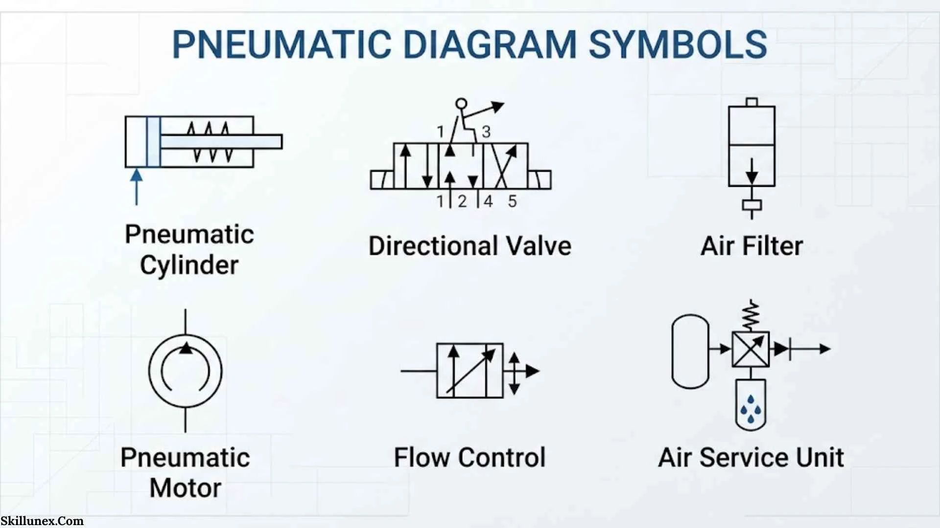
Pneumatic diagram symbols are the quiet language behind machines that move, clamp, lift, sort, press, and automate. At first glance, a pneumatic schematic can look like a maze of boxes, arrows, lines, and small marks. Once you understand the visual logic, however, the diagram begins to tell a clear story about pressure, airflow, motion, and control.
These symbols matter because engineers around the world need a common way to describe fluid power systems without drawing every physical component in detail. Modern pneumatic symbols are standardized mainly through the ISO 1219 family of standards, creating a technical language that can cross companies, countries, and industries.
This guide explains pneumatic diagram symbols from the ground up, including valve symbols, cylinder symbols, air preparation symbols, flow-control symbols, actuators, historical development, psychological aspects of technical symbolism, cultural context, common mistakes, and practical ways to read a complete pneumatic circuit.
Pneumatic Diagram Symbols: (Quick Answer)
Pneumatic diagram symbols are standardized graphical representations of components used in compressed-air systems. They show the function and connections of valves, cylinders, filters, regulators, compressors, flow controls, actuators, and other devices. ISO 1219 provides the main international framework for creating and using these symbols in fluid-power circuit diagrams.
Quick Facts About Pneumatic Diagram Symbols
| Aspect | Information |
| Origin | Developed as part of the wider standardization of fluid-power engineering symbols |
| Main international reference | ISO 1219, especially ISO 1219-1 for graphical symbols and ISO 1219-2 for circuit diagrams |
| Historical significance | Created a shared visual language for describing fluid-power systems |
| Main meaning | A symbol represents the function, connections, or operating characteristics of a pneumatic component |
| Spiritual meaning | There is no recognized spiritual meaning assigned to pneumatic engineering symbols |
| Cultural importance | They represent the global culture of engineering standardization and technical communication |
| Modern usage | Manufacturing, automation, robotics, packaging, automotive production, process machinery, maintenance, and engineering education |
ISO 1219-1:2012 defines the basic graphical elements and rules for fluid-power symbols. ISO 1219-2:2012 establishes rules for drawing hydraulic and pneumatic circuit diagrams using those symbols. ISO 1219-3:2016 deals with the generation and combination of connected symbol modules.
What Are Pneumatic Diagram Symbols?
Pneumatic diagram symbols are simplified graphical representations of pneumatic components and their functions.
A pneumatic system may contain dozens of physical parts:
- Air compressor
- Receiver tank
- Filter
- Pressure regulator
- Lubricator
- Directional control valve
- Solenoid valve
- Pneumatic cylinder
- Rotary actuator
- Flow-control valve
- Check valve
- Pressure-relief device
- Silencer
- Sensors
- Tubing and connections
Drawing every component as it actually looks would make an engineering drawing difficult to read. Instead, a schematic uses standardized symbols.
The symbol does not usually try to show what the component looks like.
It shows what the component does.
That distinction is one of the most important ideas in pneumatic schematic reading.
Why Engineers Use Symbols Instead of Pictures
Imagine trying to design an automated packaging machine using realistic pictures of every valve and cylinder.
The drawing would quickly become enormous.
A standardized symbol is much smaller and more useful. It tells an engineer:
- How many ports a valve has
- How many positions it has
- Where air can flow
- Whether a port is normally open or closed
- How the valve is actuated
- Whether flow is restricted
- Whether a cylinder is single-acting or double-acting
- How components are connected
This is why pneumatic symbols are closer to a technical language than to ordinary illustrations.
The Main Standard: ISO 1219
The ISO 1219 family is central to modern fluid-power symbolization.
ISO 1219-1:2012 covers graphical symbols for fluid-power components and includes rules for developing those symbols. ISO lists this edition as the published version, with Amendment 1 issued in 2016.
ISO 1219-2:2012 covers circuit diagrams and was confirmed by ISO in 2023. It explains how pneumatic and hydraulic circuits should be represented using the graphical symbols defined under ISO 1219-1.
ISO 1219-3:2016 adds rules for creating and combining symbol modules for connected components. ISO states that this edition was confirmed in 2022.
Other standards and industry conventions may also appear in real-world drawings. For example, manufacturers may provide symbol libraries based on ISO or other national standards. Parker documentation notes the use of ISO 1219 alongside BS 2917 and NF E04-057 for pneumatic symbols.
How to Read a Pneumatic Diagram
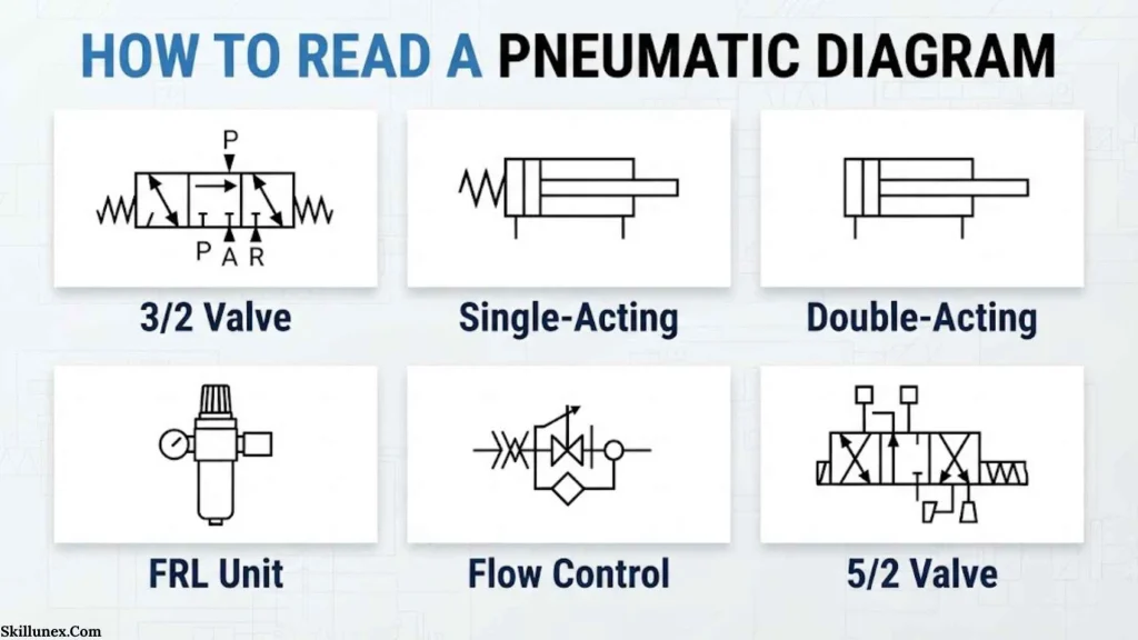
The easiest way to read pneumatic diagram symbols is to stop looking at the entire schematic at once.
Instead, follow the system in a logical order.
A typical pneumatic system can be understood as:
Air generation → air preparation → control → actuation → exhaust
For example:
Compressor → filter → regulator → directional valve → cylinder
This simple flow tells you much of what the machine is doing.
Find the Air Supply
Look for the symbol representing the pneumatic energy source or compressed-air supply.
The supply is the starting point of the power side of the circuit.
Find Air Preparation
Next, look for devices that clean, regulate, or prepare the air.
Common components include:
- Filter
- Regulator
- Lubricator
- Filter-regulator combination
- Pressure gauge
These components influence the quality and pressure of the air before it reaches the control components.
Find the Directional Control Valve
The directional valve determines where compressed air goes.
This is often the most visually intimidating symbol for beginners.
The secret is simple:
Count the boxes and count the ports.
A directional valve symbol is commonly drawn using adjacent squares.
The number of squares indicates the number of valve positions.
The number of ports indicates how many connection paths the valve has.
Follow the Actuator
The actuator is the part that turns pneumatic energy into useful movement.
Typical actuators include:
- Linear cylinders
- Double-acting cylinders
- Single-acting cylinders
- Rotary actuators
- Air motors
Check the Control and Exhaust Paths
Finally, examine:
- Exhaust ports
- Flow controls
- Check valves
- Pressure controls
- Sensors
- Solenoid operators
- Mechanical actuators
This reveals how the machine starts, stops, extends, retracts, slows down, or protects itself.
The Most Important Pneumatic Diagram Symbols
The following symbols form the foundation of most pneumatic circuits.
Pneumatic Cylinder Symbols
A pneumatic cylinder converts compressed air into linear motion.
There are two major types.
Single-acting cylinder
A single-acting cylinder uses compressed air to move in one direction. A spring or another external force returns the piston.
In a schematic, the cylinder symbol shows the actuator and its single working connection, with the spring represented when applicable.
Double-acting cylinder
A double-acting cylinder uses compressed air to move the piston in both directions.
It normally has two working ports.
One port supplies air to extend the cylinder. The other supplies air to retract it.
Double-acting cylinders are extremely common in automation because they provide controlled movement in both directions.
Directional Control Valve Symbols
Directional control valves are often named using a format such as:
3/2 valve
or
5/2 valve
The first number describes the number of ports.
The second number describes the number of positions.
For example:
3/2 valve = 3 ports and 2 positions
5/2 valve = 5 ports and 2 positions
Parker’s pneumatic documentation provides examples of 2/2, 3/2, 4/2, 4/3, 5/2, and 5/3 valve configurations and their port arrangements.
Understanding the Boxes
A directional control valve may appear as two or three connected squares.
Each square represents one possible valve position.
Inside the square, arrows and blocked lines show what happens to the air.
An arrow indicates a flow path.
A blocked connection indicates that the path is closed.
This gives the symbol a kind of visual grammar.
The boxes tell you where the valve can be.
The arrows tell you where the air can go.
2/2 Valve
A 2/2 valve has:
- Two ports
- Two positions
It can open or close a single flow path.
It is useful for simple on/off control.
3/2 Valve
A 3/2 valve has:
- Three ports
- Two positions
It is frequently used to control single-acting cylinders.
It can also be used for pneumatic signals and control functions.
4/2 Valve
A 4/2 valve has four ports and two positions.
It can direct pressure to one side of an actuator while connecting the opposite side to exhaust, then reverse those connections.
5/2 Valve
The 5/2 valve is one of the most familiar valves in pneumatic automation.
It has five ports and two positions.
It is commonly used to control a double-acting cylinder.
Two ports serve the actuator, while the supply and exhaust connections complete the pneumatic paths.
5/3 Valve
A 5/3 valve has five ports and three positions.
The middle position can be designed differently depending on the required circuit function.
Common center conditions include:
- Closed center
- Exhaust center
- Pressure center
The center position matters because it determines what happens to the actuator when the valve is in its neutral state.
Pneumatic Valve Actuation Symbols
A valve does not change position by itself.
Something has to command it.
The small symbols attached to the sides of a directional valve show how the valve is actuated.
Common actuation methods include:
- Push button
- Lever
- Pedal
- Roller
- Roller lever
- Solenoid
- Pneumatic pilot
- Spring return
- Mechanical actuator
Festo training material illustrates several manual and mechanical actuation methods, including push buttons, levers, pedals, rollers, plungers, and pneumatic control methods.
Manual Actuation
A human operator may press a button, move a lever, or operate a pedal.
Manual symbols are common in simple machines and maintenance controls.
Mechanical Actuation
A machine can operate a valve mechanically.
A roller lever, cam, or plunger can be positioned so that the movement of another machine part changes the valve position.
Solenoid Actuation
An electrical solenoid can move the pneumatic valve.
This is extremely common in automated systems.
It also creates the bridge between electrical control and pneumatic power.
Spring Return
A spring symbol indicates that the valve is mechanically returned toward a particular position when the activating force is removed.
Understanding the spring position is critical when reading a circuit.
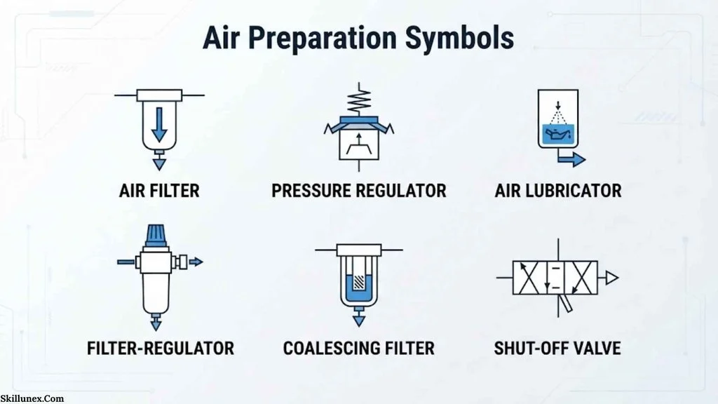
Air Preparation Symbols
Compressed air does not automatically arrive at a machine in the right condition.
It may contain moisture, particles, oil, or other contamination. Pressure may also need to be reduced and controlled.
Filter Symbol
A filter removes contaminants from compressed air.
In a pneumatic schematic, its symbol represents the filtering function rather than the physical shape of the filter housing.
Pressure Regulator Symbol
A pressure regulator controls downstream pressure.
This is important because different pneumatic components may require different working pressures.
Pressure Gauge
A gauge provides pressure information.
In many diagrams, it is associated with a regulator or service unit.
Lubricator
A lubricator can introduce a controlled amount of oil into an air stream where the application and equipment require it.
Modern systems often use lubrication only where appropriate, because many pneumatic components are designed for non-lubricated operation.
FRL Unit
You may encounter the abbreviation FRL.
It usually refers to:
Filter + Regulator + Lubricator
An FRL assembly prepares compressed air before it reaches downstream equipment.
Flow-Control Pneumatic Symbols
Pressure tells you about force potential.
Flow often has a major influence on actuator speed.
This is why flow-control symbols are essential.
Flow-Control Valve
A flow-control valve restricts airflow.
By changing the amount of air entering or leaving an actuator, the valve can influence its movement speed.
One-Way Flow Control
A common pneumatic arrangement allows relatively free flow in one direction while restricting flow in the opposite direction.
This is often represented by combining a restriction with a check-valve function.
Check Valve
A check valve allows air to flow in one direction while preventing reverse flow.
The symbol communicates this one-way behavior.
Silencer
Exhaust air can create significant noise.
A silencer, sometimes called a muffler, can be installed at an exhaust port to reduce noise.
The symbol represents the exhaust treatment function rather than the external shape of the device.
Pressure-Control Symbols
Pressure-control devices help manage the force and operating conditions of a pneumatic system.
Common examples include:
- Pressure regulators
- Pressure-relief valves
- Pressure switches
- Sequence valves
- Pressure-control elements
A pressure-related symbol should not be confused with a flow-control symbol.
A useful mental shortcut is:
Pressure influences force.
Flow influences speed.
This is not the complete story of pneumatic behavior, but it is a useful starting point.
Pneumatic Lines and Connections
Lines may look simple, but they carry important information.
A pneumatic circuit can contain:
- Working lines
- Control lines
- Supply lines
- Exhaust lines
- Pilot lines
- Connections
- Crossings
Connected Lines
When lines are intentionally connected, the drawing convention makes that relationship clear.
Crossing Lines
Two lines may cross without being connected.
This is one reason diagram conventions matter.
Never assume that every crossing line represents a pneumatic connection.
Always inspect the connection notation used in the drawing.
Exhaust Ports
Exhaust ports show where compressed air leaves the circuit.
Exhaust paths are especially important when analyzing cylinder movement.
Types and Variations of Pneumatic Diagram Symbols
| Component | Visual idea | Function | Typical application |
| Compressor | Pneumatic energy-source representation | Produces compressed air | Factory air supply |
| Filter | Filter element representation | Removes contaminants | Air preparation |
| Regulator | Pressure-control representation | Controls downstream pressure | Machine air supply |
| Gauge | Measuring-device representation | Indicates pressure | Monitoring |
| Check valve | One-way flow representation | Prevents reverse flow | Flow isolation |
| Flow control | Restriction representation | Controls airflow | Cylinder speed |
| Cylinder | Actuator representation | Converts air pressure into linear motion | Clamping, pushing, lifting |
| Rotary actuator | Rotary motion representation | Produces angular motion | Turning mechanisms |
| 3/2 valve | Three-port, two-position representation | Controls simple pneumatic functions | Single-acting cylinders |
| 5/2 valve | Five-port, two-position representation | Reverses airflow | Double-acting cylinders |
| 5/3 valve | Five-port, three-position representation | Provides three control states | Advanced actuator control |
| Solenoid | Electrical actuation representation | Electrically shifts a valve | Automation |
| Spring | Mechanical return representation | Returns a valve or component | Fail or default position |
The Symbolic Meaning of Pneumatic Diagrams
The word “symbol” can make pneumatic diagrams sound more mysterious than they really are.
A pneumatic symbol does have meaning, but its meaning is technical.
It is not normally a religious, mystical, or spiritual symbol.
A triangle, arrow, square, circle, line, or spring-like marking has a defined engineering purpose within the relevant standard and drawing convention.
This distinction is important because a technical symbol should be interpreted from the standard and the circuit context, not from personal symbolism.
Symbolism at the Technical Level
A pneumatic schematic is a form of abstraction.
The physical machine might contain metal bodies, seals, springs, coils, tubes, sensors, and moving pistons.
The diagram compresses all of that physical complexity into a visual language.
In that sense, the diagram has a powerful symbolic quality:
A small mark can represent a large physical process.
A few lines may represent an entire production sequence.
A small valve symbol may represent a device capable of controlling thousands of machine cycles.
That is one reason technical diagrams can feel almost like a visual language.
Psychological Meaning of Pneumatic Symbols
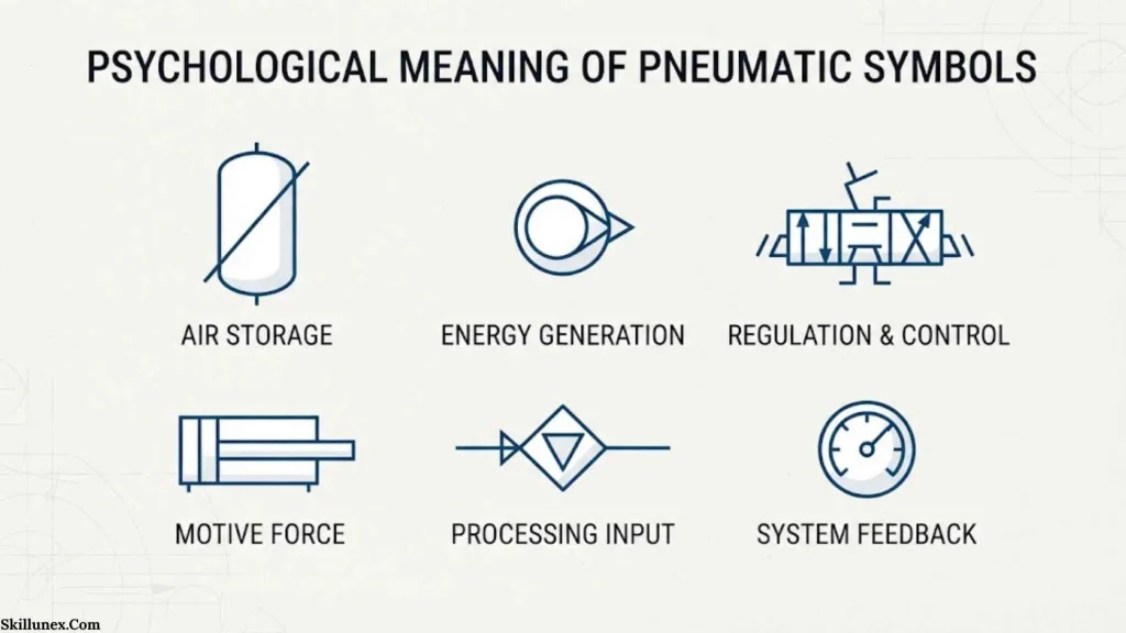
Human beings are naturally good at recognizing patterns.
Engineers use this ability when reading schematics.
After enough practice, a technician can see a 5/2 valve symbol and immediately recognize the likely role it plays in the circuit without consciously reading every line.
This is an example of visual pattern recognition.
From Beginner to Expert
A beginner sees:
“Several boxes and arrows.”
An experienced technician sees:
“Five ports, two positions, solenoid actuation, spring return, cylinder control.”
The information has not changed.
The reader has changed.
Knowledge turns visual complexity into familiar patterns.
Why Standardization Reduces Mental Effort
Standardized symbols reduce the amount of information an engineer must relearn.
This is similar to learning traffic signs.
Once you understand the visual system, you do not need a paragraph explaining every symbol.
You recognize the pattern.
The same principle applies to pneumatic diagrams.
Pneumatic Diagram Symbols Across Different Cultures
Modern pneumatic symbols should not be incorrectly attributed to ancient cultures as if Ancient Egypt, Greece, Rome, India, China, or Indigenous societies used ISO pneumatic schematics.
They did not.
Modern pneumatic diagram symbols belong to the history of industrial engineering and technical standardization.
However, the broader history of air, pressure, mechanics, and automation reaches much further back.
Ancient Egypt
Ancient Egyptian civilization used sophisticated mechanical technologies, including devices involving levers, lifting systems, water management, and construction technology.
There is no historical basis for saying that ancient Egyptians used modern pneumatic circuit symbols.
The important connection is broader: humans have long searched for ways to control forces that are not always visible.
Compressed air became one of many technologies through which that invisible force could later be controlled.
Ancient Greece
Ancient Greek and Hellenistic engineers made important contributions to mechanics and pneumatics.
The hero of Alexandria is especially relevant.
His work known as Pneumatica described devices that used air, water, pressure, and mechanical principles. Historical scholarship describes his pneumatic devices and automata as important examples of ancient mechanical ingenuity.
The hero’s work is fascinating because it connects engineering with wonder.
His machines could create surprising effects using principles that were not immediately visible to observers.
But these devices should not be confused with modern industrial pneumatics.
The connection is historical and conceptual, not a direct line from ancient drawings to today’s ISO symbols.
Roman Culture
Roman engineers inherited and developed Greek and Hellenistic mechanical knowledge.
Roman engineering is particularly famous for large infrastructure, hydraulics, construction, military engineering, and mechanical technology.
Ancient Roman technological traditions contributed to the long history of mechanical engineering, but Roman engineers did not use modern pneumatic schematic conventions.
Eastern Traditions
China, the Islamic world, India, and other regions developed important mechanical technologies, automation concepts, water devices, clocks, pumps, and other machines over many centuries.
The medieval Islamic engineer al-Jazari, for example, is well known for detailed descriptions and illustrations of mechanical devices.
These traditions demonstrate an important truth:
The human desire to represent and control mechanical processes is much older than modern industrial standards.
The exact graphical language used in modern pneumatic schematics, however, is a product of modern engineering standardization.
Indigenous Traditions
Indigenous societies around the world developed sophisticated technologies adapted to local environments.
These included tools, water management, hunting technologies, construction methods, transportation systems, and material-processing techniques.
It would be misleading to assign ISO pneumatic symbolism to these traditions.
A better historical comparison is that many cultures independently developed ways of representing knowledge through visual marks, diagrams, patterns, and practical instruction.
Modern engineering symbols are one highly specialized example of that wider human habit.
Pneumatic Diagram Symbols in Mythology and Folklore
There is no established mythology in which ISO pneumatic symbols such as 3/2 valves, 5/2 valves, regulators, or cylinders have traditional religious meanings.
However, the underlying idea of air as an invisible force has appeared in many cultures.
Air, breath, wind, and spirit have often been connected in human thought.
The exact meanings differ between traditions, and they should not be collapsed into one universal interpretation.
Engineering changed the relationship between humans and invisible forces.
A pressure gauge makes air pressure measurable.
A valve makes airflow controllable.
A cylinder makes pneumatic force visible through motion.
A schematic makes the entire process mentally visible.
That transformation from invisible force to measurable system is one of the most interesting cultural stories surrounding pneumatics.
Pneumatic Symbols in Art, Literature and Popular Culture

Pneumatic diagrams are rarely used as cultural symbols in the same way that hearts, stars, skulls, or religious icons are.
Their appearances are more closely connected with:
- Industrial art
- Engineering textbooks
- Technical manuals
- Patent drawings
- Factory documentation
- Robotics
- Steampunk design
- Industrial fashion
- Engineering-themed tattoos
- Technical illustrations
- Maker culture
- Automation and robotics media
Pneumatic Diagrams in Industrial Art
Technical drawings can have a distinctive visual beauty.
The repeated geometry, precise lines, arrows, circles, and modular shapes create a visual order that appeals to people who enjoy engineering and machinery.
Pneumatic Symbols in Tattoos
Some people choose technical diagrams, valves, cylinders, gears, or machine schematics as tattoos.
In this context, the meaning becomes personal.
Someone may associate a pneumatic symbol with:
- Engineering
- Mechanical skill
- Automation
- A career
- Industrial work
- Creativity
- Precision
- Problem solving
- A particular machine or profession
Those meanings belong to the individual rather than to an official symbolic tradition.
Spiritual and Dream Meaning of Pneumatic Diagram Symbols
There is no accepted spiritual dictionary for pneumatic diagram symbols.
If someone dreams about a valve, cylinder, compressed air system, or machine schematic, the interpretation should be treated as personal rather than as an established spiritual fact.
A dream about a valve might remind a person of control, release, restriction, pressure, or decision-making.
A cylinder might personally suggest movement or mechanical force.
Compressed air might evoke energy, pressure, or something invisible becoming active.
These are psychological associations, not scientific or religious definitions.
A Useful Psychological Approach to Dreams
Instead of asking:
“What does a 5/2 valve universally mean spiritually?”
A better question is:
“What does this machine, valve, pressure, or movement mean to me?”
That approach respects personal experience without presenting speculation as established fact.
Positive and Negative Meanings of Pneumatic Diagram Symbols
Because pneumatic symbols are technical rather than mystical, their positive and negative meanings are best understood through engineering context.
| Positive Meaning | Negative or Cautionary Meaning |
| Precision | Incorrect interpretation |
| Control | Excessive restriction |
| Automation | System complexity |
| Efficiency | Air leakage |
| Movement | Uncontrolled motion |
| Reliability | Poor maintenance |
| Standardization | Confusing non-standard drawings |
| Safety through controlled design | Unsafe pressure or incorrect installation |
| Clear communication | Ambiguous documentation |
| Problem solving | Faults hidden by poor diagnostics |
A symbol itself is rarely “good” or “bad.”
Its meaning depends on the system around it.
A pressure regulator can represent careful control in one circuit and an incorrect pressure setting in another.
A valve can provide safe control when correctly designed, yet create dangerous movement if the circuit is misunderstood.
Why Humans Are Attracted to Pneumatic Diagram Symbols
There is a surprisingly human reason technical diagrams can become fascinating.
They turn invisible processes into something the mind can see.
Compressed air is invisible.
Pressure cannot be seen directly.
Airflow through a small passage is normally invisible.
Yet a pneumatic diagram gives these hidden processes a visual structure.
The result is powerful.
A technician can look at a diagram and mentally simulate the machine.
Air enters here.
The valve changes position.
Pressure reaches this side of the cylinder.
The piston extends.
The valve shifts.
Air exhausts.
The piston retracts.
The diagram becomes a story of cause and effect.
Pattern Recognition
Humans are strongly attracted to patterns.
A pneumatic schematic contains repeated visual rules.
Squares represent valve positions.
Arrows represent flow paths.
Lines represent connections.
Symbols represent functions.
Once learned, these patterns allow complex systems to become easier to understand.
The Emotional Appeal of Machines
Machines also have emotional associations.
For some people, pneumatic systems represent:
- Strength
- Precision
- Motion
- Industry
- Reliability
- Human ingenuity
- Automation
- Technical creativity
That emotional response is not part of the ISO standard, but it helps explain why industrial diagrams can have visual appeal beyond their practical purpose.
Modern Uses of Pneumatic Diagram Symbols
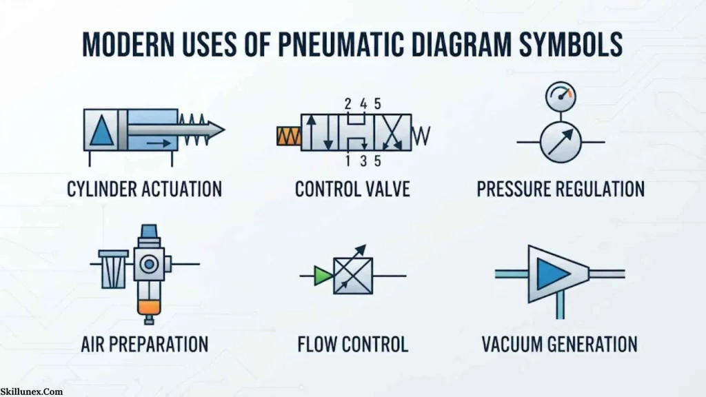
Pneumatic symbols remain important in modern industrial automation.
They are used in:
- Factory automation
- Automotive manufacturing
- Packaging machines
- Bottling equipment
- Material handling
- Robotics
- Pick-and-place systems
- Clamping systems
- Pressing equipment
- Assembly machinery
- Food-processing equipment
- Medical manufacturing equipment
- Process machinery
- Maintenance documentation
- Engineering education
Pneumatic systems remain important because compressed air can provide fast, repeatable actuation in many industrial applications. Modern training programs continue to teach compressed-air generation, air preparation, pneumatic actuators, valves, and electro-pneumatic control systems.
How to Read a 5/2 Pneumatic Valve Symbol
A common beginner question is how to understand a 5/2 valve.
Start with the name.
5/2 means five ports and two positions.
Then examine the two boxes.
Each box represents one valve position.
Inside each box, follow the arrows.
The arrows show which ports are connected in that position.
Then look outside the boxes.
The symbols on the left and right tell you how the valve changes position.
For example, one side may show a solenoid and the other side a spring.
This tells you that an electrical signal moves the valve one way, while the spring returns it when the signal is removed.
The important lesson is:
Do not memorize the shape alone. Read the flow paths.
How to Read a Pneumatic Cylinder Circuit
Suppose a circuit contains:
Air supply → 5/2 valve → double-acting cylinder
The logic is straightforward.
In one valve position, compressed air enters one side of the cylinder.
The opposite side exhausts.
The piston moves in one direction.
When the valve changes position, the air paths reverse.
The cylinder moves in the opposite direction.
If flow-control valves are added, the speed of movement can be adjusted.
If sensors are added, the control system can detect piston position.
If solenoid valves are used, an electrical controller can command the pneumatic movement.
This is the basic foundation of electro-pneumatic automation.
Common Mistakes When Reading Pneumatic Symbols
Treating the Symbol Like a Picture
A valve symbol does not normally resemble the physical valve.
Read its function instead.
Confusing Ports With Positions
In a valve designation such as 5/2:
5 = ports
2 = positions
Do not reverse them.
Ignoring the Center Position
With a 5/3 valve, the center condition is critical.
It determines what happens when the valve is neutral.
Forgetting the Actuator
A valve may look correct, but its actuation method changes how the circuit behaves.
Always inspect the solenoid, spring, pilot, lever, roller, or other actuator.
Assuming Crossing Lines Are Connected
Follow the drawing convention carefully.
A crossing does not automatically mean a connection.
Confusing Flow Control With Pressure Control
Flow control is generally associated with managing airflow and actuator speed.
Pressure control is associated with managing pressure and therefore the force available from an actuator.
Ignoring Exhaust
Exhaust paths are part of the circuit.
A cylinder cannot behave correctly if the exhaust path is misunderstood.
Pneumatic Diagram Symbols vs Hydraulic Symbols
Pneumatic and hydraulic schematics use closely related graphical principles because both belong to fluid power.
ISO 1219 applies to fluid-power symbolization, and ISO 1219-2 specifically covers hydraulic and pneumatic circuit diagrams.
The major difference is the working medium.
Pneumatics use gases, normally compressed air.
Hydraulics use liquids, commonly hydraulic oil or another hydraulic fluid.
The symbols may therefore look similar, but the physical behavior of the systems is different.
Pneumatics are often valued for speed, cleanliness in suitable applications, and relatively simple actuation.
Hydraulics are commonly chosen where high force and controlled power transmission are required.
Pneumatic Diagram Symbols vs Electrical Symbols
Modern machines frequently combine pneumatics and electrical control.
This creates electro-pneumatic systems.
The electrical side may contain:
- Push buttons
- Relays
- Sensors
- PLC inputs
- PLC outputs
- Solenoids
- Electrical logic
The pneumatic side may contain:
- Valves
- Cylinders
- Regulators
- Filters
- Flow controls
- Air supply
The electrical system decides what should happen.
The pneumatic system provides the physical movement.
That relationship is central to modern industrial automation.
Interesting Facts About Pneumatic Diagram Symbols
- The symbols are functional rather than pictorial. A valve symbol is designed to explain operation, not reproduce the physical appearance of the valve.
- ISO 1219 is part of a larger international language of engineering graphics. ISO describes graphical conventions as important for communication across engineering, manufacturing, and design.
- ISO 1219 has a long history. Earlier versions included ISO 1219:1976 and ISO 1219-1:1991 before later revisions.
- Modern pneumatic symbolism has ancient conceptual relatives. Hero of Alexandria described pneumatic devices many centuries before industrial pneumatic automation existed.
- A valve’s boxes matter. In directional control valve symbols, the boxes represent different valve positions.
- Arrows are functional clues. They show flow paths within a valve position.
- The same basic visual language can describe different physical industries. Fluid-power symbolism is used across pneumatic and hydraulic applications.
- Symbol modules can be combined. ISO 1219-3 specifically provides rules for generating and combining connected symbols.
- A schematic can reveal machine behavior without showing the machine itself. This is one of the great strengths of engineering abstraction.
- A technician eventually reads symbols almost like sentences. Experience changes the diagram from a collection of shapes into a sequence of actions.
Frequently Asked Questions
What are pneumatic diagram symbols?
Pneumatic diagram symbols are standardized graphical representations of components and functions in compressed-air systems. They represent valves, cylinders, filters, regulators, flow controls, air supplies, actuators, and other pneumatic devices.
What standard is used for pneumatic symbols?
ISO 1219 is the major international reference for fluid-power graphical symbols and circuit diagrams. ISO 1219-1 covers graphical symbols, while ISO 1219-2 covers circuit diagrams. ISO 1219-3 addresses symbol modules and connected symbols.
What does 5/2 mean on a pneumatic valve?
A 5/2 valve has five ports and two positions. It is commonly used to control a double-acting pneumatic cylinder by directing compressed air alternately to the two cylinder ports.
What does 3/2 mean in pneumatics?
A 3/2 valve has three ports and two positions. It is commonly used for single-acting cylinders, pneumatic signals, and other simple control functions.
What is the difference between pneumatic symbols and pneumatic components?
A pneumatic component is the physical device installed in a machine. A pneumatic symbol is the graphical representation used to describe that device or its function in a technical diagram.
Do pneumatic diagram symbols have spiritual meanings?
No recognized engineering or ISO system assigns spiritual meanings to pneumatic diagram symbols. Personal or artistic interpretations are possible, but they should not be presented as established cultural or religious meanings.
Conclusion
Pneumatic diagram symbols are much more than a collection of boxes, arrows, and lines. They form a practical visual language that allows engineers and technicians to describe invisible forces, controlled airflow, and machine movement with remarkable economy.From Hero of Alexandria’s ancient experiments with pneumatic devices to today’s automated factories, humans have continued to find ways to control air and turn it into useful motion.
Learning these symbols means learning how a machine thinks: where energy enters, how it is controlled, where it moves, and what happens when the control changes.Once the visual language becomes familiar, a complicated pneumatic schematic stops looking like a maze and starts looking like a story written in pressure, flow, motion, and control.

Caleb Thornton
I’m Caleb Thornton, a researcher and content writer who loves exploring fascinating subjects and sharing what I learn with readers. My interests include natural places, lakes, symbols, culture, history, and the stories that make ordinary topics more meaningful.
When I write an article, I try to go beyond a basic answer. I look for useful facts, relevant context, and details that can help readers understand the subject more completely.
My purpose is simple: I want every article I contribute to provide genuine value, satisfy the reader’s curiosity, and make discovering new information enjoyable.
## Books by Caleb Thornton
* Symbols & Meanings: Exploring the Signs We See Every Day
* Lakes of the World: Nature, Beauty & Exploration